This tip is the follow up to the April 2016 Tip of the Month (TOTM) which investigated the benefits of having a water-draw in a condensate stabilizer column. It will use a commercial simulation software to simulate the performance of an operating stabilizer. In order to take into account the non-ideality of water, the tip will perform three-phase (vapor, liquid hydrocarbon, and aqueous phases) calculations on the trays with excessive water rates. Specifically, it will study the influence of the column temperature profile and water partial pressure profile on the optimum location of water-draw tray in the column. It will also study the impact of the upstream 3-phase separator temperature on the reboiler, condenser, feed-stabilized condensate heat exchanger duties, and the reflux pump power. The tip will present a summary of the computer simulation results and the key diagrams for the same case study.
Case Study
Table 1 presents the compositions (mol %) of a raw condensate mixture studied. This table also presents the required heavy end properties (Molecular Weight, Specific Gravity, and Volume Average Boiling Point) and the conditions of the feed stream.
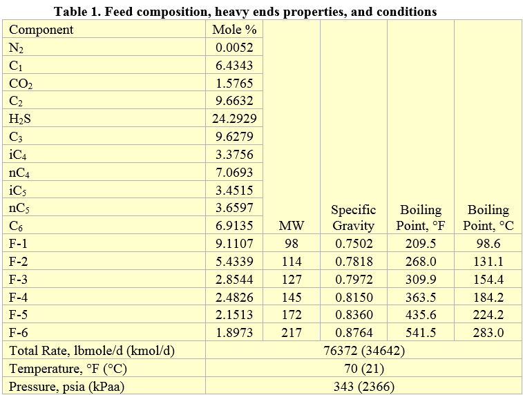
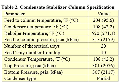
Figure 1 presents a simplified process flow diagram for the case study. The tip utilizes the front mixer to vary the feed water rate for the simulation purpose only. The use of the heat exchanger (HEX) will lower the reboiler and condenser duties and reflux pump power. The addition of a 3-phase separator upstream of the HEX removes essentially all excess water. It also allows investigating the impact of feed temperature on the performance of the column. Table 2 presents the stabilizer column specifications. Note the difference between water draw from within the column and water drain from the V-4 reflux drum. Reference [1] presents a good overview of a water-draw in a condensate stabilizer column.
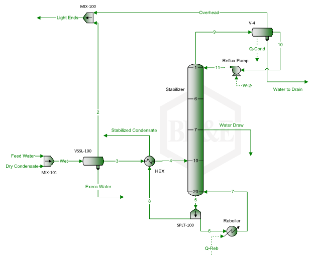
Figure 1. A simplified stabilizer column with side water-draw
Based on the data in Tables 1 and 2, and the process flow diagram of Figure 1, the tip performed simulation using the Soave-Redlich-Kwong (SRK) equation of state [2] in ProMax [3] software.
Simulation Results – Water Partial Pressure and Temperature Profiles:
Figures 2a and 2b present the water partial pressure profile for two feed water flow rates of 1200 and 1500 lbmole/d (545 and 681 kmol/d), respectively. Both figures present water partial pressure for cases of no water-draw and water-draw at tray of 7 or 8. In these figures, a large spike of water partial pressure is observed for the cases of no water-draw tray.
For the lower water flow rate (Figure 2a), draw tray 8 still shows a smaller spike of water partial pressure indicating draw tray 8 in not the optimum choice. The water partial pressure profile is smooth for draw tray 7 indicating draw tray 7 is the optimum location for this flow rate.
For the higher water flow rate (Figure 2b), draw tray 7 still shows a smaller spike of water partial pressure indicating draw tray 7 in not the optimum choice. The water partial pressure profile is smooth for draw tray 8 indicating draw tray 8 is the optimum location for this flow rate. Analyzing these two figures indicates that water partial pressure profile is a handy tool in locating the optimum water-draw tray.
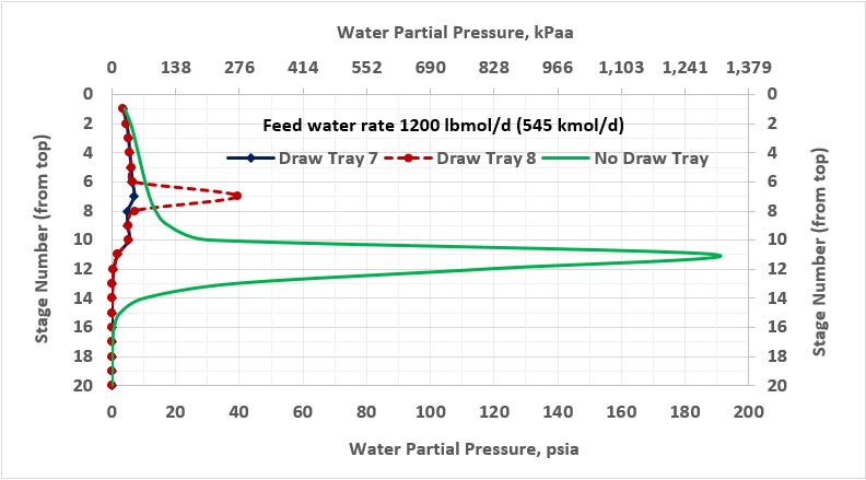
Figure 2a. Water partial pressure profile in the stabilizer column for three cases
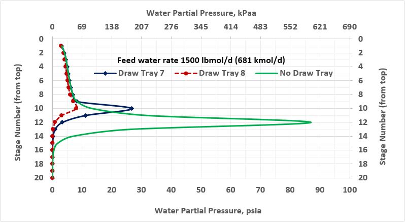
Figure 2b. Water partial pressure profile in the stabilizer column for three cases
Similarly, Figures 3a and 3b present the column temperature profile for two feed water flow rates of 1200 and 1500 lbmole/d (545 and 681 kmol/d), respectively. Both figures show the column temperature profile for no water-draw and water-draw tray of 7 or 8. In these figures, a large spike of temperature profile is observed for the cases of no water-draw tray. These spikes are not as large as the ones observed for water partial pressure.
For the lower water flow rate (Figure 3a), draw tray 8 still shows a smaller spike of the column temperature indicating draw tray 8 is not the optimum choice. While the column temperature profile is smooth for draw tray 7 indicating this draw tray 7 is the optimum location for this flow rate.
For the higher water flow rate (Figure 3b), draw tray 7 still shows a much smaller spike of the column temperature indicating draw tray 7 is not the optimum choice. The column temperature profile is smoother for draw tray 8 indicating draw tray 8 is the optimum location for this flow rate. Analysis of these two figures indicates that the column temperature profile is also a handy tool in locating the optimum of the optimum water-draw tray. These four figures also confirm the optimum locations of draw trays reported in the previous tip.
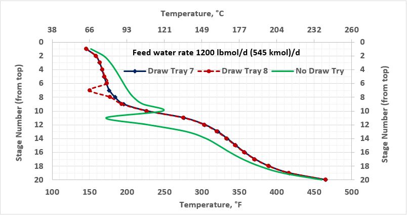
Figure 3a. Temperature profile in the stabilizer column with and without side water-draw tray
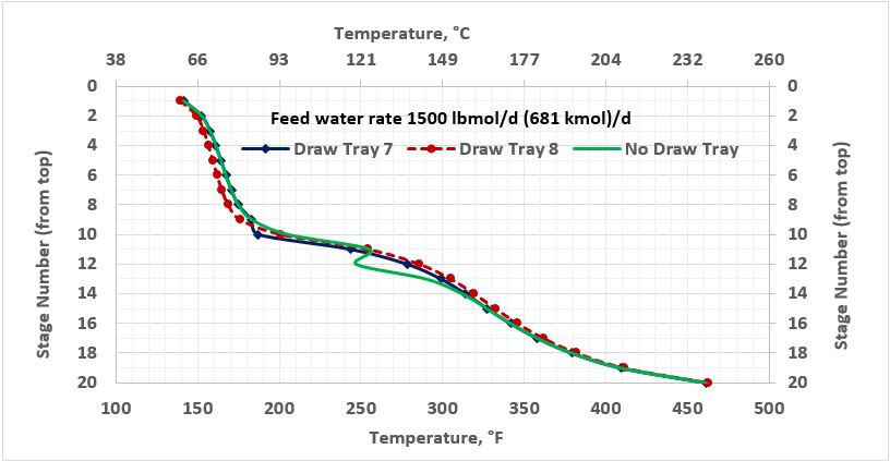
Figure 3b. Temperature profile in the stabilizer column with and without side water-draw tray
Simulation Results – Impact of Raw Condensate Feed Temperature:
Normally, an upstream three-phase separator as shown in Figure 1 is used to remove light gases and free water from the condensate to minimize the reboiler, condenser, the feed-stabilized condensate heat exchanger (HEX) duties, and the reflux pump power. A properly sized separator may also eliminate the need for a water-draw tray.
To investigate the impact of feed temperature on the performance of the column, the tip performed simulation for feed temperature from 70 to 120°F (21 to 49°C) with an increment of 10°F (5.5°C). Tables 3a and 3b present the simulation results based on the input data of Tables 1 and 2.
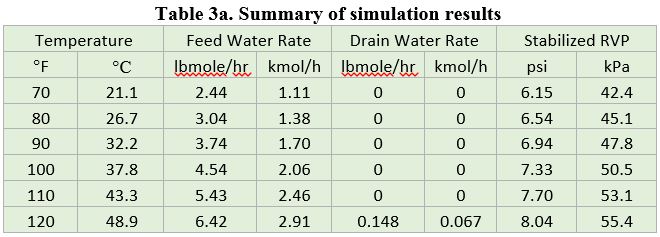
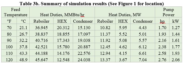
Table 3a and Figure 4 indicate clearly that as the feed temperature increases, the dissolved water in the un-stabilized condensate increases. Most of the feed water leaves the column with light gases from top of the column and a small amount with the stabilized condensate from the bottom. No water leaves from water-draw tray. With the exception of high feed temperature (120°F=48.9°C), no water leaves the column by the water drain from the top of the column.
Figures 5 through 7 present the impact of feed temperature on the stabilized condensate Reid vapor pressure (RVP), heat the transfer equipment duties, and the reflux pump power requirement.
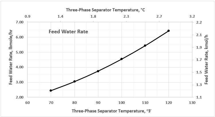
Figure 4. Feed water rate as a function of 3-phase separator temperature
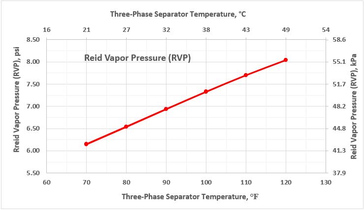
Figure 5. Stabilized condensate RVP as a function of 3-phase separator temperature
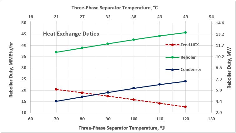
Figure 6. Heat exchange duties as a function of 3-phase separator temperature
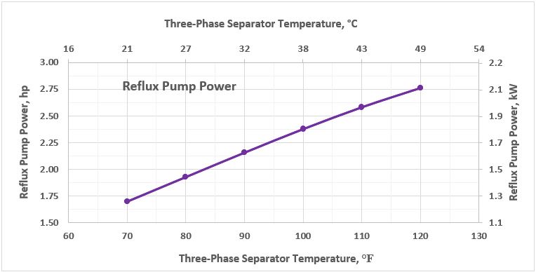
Figure 7. Reflux pump power as a function of 3-phase separator temperature
With exception of the HEX duty, in all cases the increase in feed temperature increases the stabilized condensate RVP, the reboiler and condenser duties and the reflux pump power requirement.
Conclusions:
The simulation results for the case studies demonstrated the effectiveness of side water-draw and the importance of water draw location in the column. Based on the results obtained, this tip presents the following observations.
- Water partial pressure profile in the column is an excellent tool for determining the optimum location of water-draw.
- Column temperature profile can also provide guidance for the optimum location of water-draw tray.
- The previous tip determined the optimum location of water-draw try by maximizing liquid water removal and minimizing the reboiler and condenser duties. This tip confirms the reported optimum location of water-draw tray of the previous tip by plotting the water partial pressure and column temperature profile.
- Installing a properly sized free water knockout drum (three-phase separator) minimizes the feed water rate to the stabilizer column. This ensures easier/less troublesome operation with lower utility (reboiler and condenser duties and reflux pump power) cost.
- Installing properly sized free water knockout (three phase separator) separator may also eliminate the need for water-draw. In this case most of water leaves with light gases from top of column. Only small amount of water leaves with the stabilized condensate from the bottom of column.
- As the feed temperature increases the dissolved water in the raw condensate increases. The increase in feed water rate increases the reboiler and condenser duties, the reflux pump power, and the stabilized condensate RVP. This is important for sizing the equipment and flexibility of operation.
- As the feed temperature increases the HEX duty decreases.
Part 3 (follow-up of this tip) will investigate the performance of a non-refluxed stabilizer column.
By: Dr. Mahmood Moshfeghian
Reference:
- Campbell, J.M., Gas Conditioning and Processing, Volume 2: The Equipment Modules, 9th Edition, 2nd Printing, Editors Hubbard, R. and Snow–McGregor, K., Campbell Petroleum Series, Norman, Oklahoma, 2014.
- Soave, G., Chem. Eng. Sci. 27, 1197-1203, 1972.
- ProMax 3.2, Bryan Research and Engineering, Inc., Bryan, Texas, 2016.
To learn more about similar cases and how to minimize operational problems, we suggest attending our G4 (Gas Conditioning and Processing), G5 (Advanced Applications in Gas Processing), PF81 (CO2 Surface Facilities), and PF4 (Oil Production and Processing Facilities), courses.
PetroSkills offers consulting expertise on this subject and many others. For more information about these services, visit our website at http://petroskills.com/consulting, or email us at consulting@PetroSkills.com

Is there any other details about this subject in different languages?
Can I found any other details about this subject in other languages?
[…] M., May 2016 tip of the month, PetroSkills | John M. Campbell, […]