In the December 2014 tip of the month (TOTM) [1], we discussed troubleshooting of gas-liquid separators for removal of liquids from the gas stream leaving the separator. There are two methods for sizing gas-liquid separators: 1. Droplet settling theory method, 2. Souders-Brown approach. Historically the Souders-Brown equation has been employed as it can provide reasonable results and is easy to use, but has shortcomings in terms of quantifying separator performance. References [2-4] provide the details on the droplet settling theory methods which can be used to more accurately quantify separator performance. The Souders-Brown method is limited in that it is based on the average droplet size, but cannot quantify the amount of liquid droplets exiting the gas gravity section.
In this TOTM, we will focus on the application of Souders-Brown approach in gas-liquid separators and present diagram, simple correlations and tables to estimate the Souders-Brown equation constant, KS (the so called sizing parameter). We will consider both vertical and horizontal gas-liquid separators. Knowing the actual gas flow rate through the vessel, one can use KS parameter to determine the maximum allowable gas velocity through the vessel and determine the required separator diameter. One can also use the appropriate value of KS to size the mist extractor in the vessel. The performance of a gas-liquid separator is highly dependent on the value of KS; therefore, the choice of appropriate KS –values is important.
Gas Gravity Separation Section
The gas gravity separation section of a separator has two main functions:
- Reduction of entrained liquid load not removed by the inlet device
- Improvement / straightening of the gas velocity profile.
Most mist extractors have limitations on the amount of entrained liquid droplets that can be efficiently removed from the gas, thus the importance of the gas gravity section to remove the liquids to an acceptable level upstream of the mist extractor. This is particularly important for separators handling higher liquid loads. For scrubber applications with low liquid loadings, the KS –values will be primarily dependent on the mist extractor type, and the gas gravity separation section becomes less important. For the higher liquid load applications, i.e. conventional separators, there are two approaches for sizing the gravity separation section to remove liquid droplets from the gas:
- The Souders-Brown approach (Ks Method)
- Droplet settling theory
The Souders-Brown Approach
If we consider a spherical liquid droplet with a diameter of DP in the gas phase two forces as shown in Figure 1 act on it. The drag force, FD, is exerted by flow of gas and gravity force, FG, is exerted by the weight of droplet. The drag force acts to entrain the liquid droplet while the gravity force acts to pull it down and separating it from the gas phase.
![Figure 1. Schematic of the forces acting on a liquid droplet in the gas phase [5]](http://www.jmcampbell.com/tip-of-the-month/wp-content/uploads/2015/08/fig1.png)
Figure 1. Schematic of the forces acting on a liquid droplet in the gas phase [5]
![]() (1)
(1)
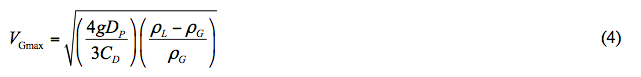
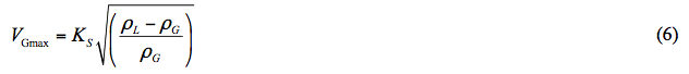
As presented in the Appendix, substitution of expressions for the drag and gravity forces in Equation 1, the maximum allowable gas velocity, VGmax, which prevents entrainment of liquid is obtained.
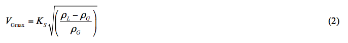
Equation 2 is called Souders-Brown [6] equation and KS is referred to as the design or sizing parameter. The terms ρG and ρL are the gas phase and liquid phase densities, respectively.
Once the maximum gas velocity, VGmax, through the vessel is determined by Equation 2, one can calculate the minimum vessel diameter, Dmin by Equation 3.
![]()
Where:
FG = Fraction of cross section area available for gas flow (FG = 1 for vertical separators and is a function of liquid height for horizontal separators)
qa = Gas flow rate at the actual flowing condition
The Design Parameter, KS
The design parameter, KS, in the Souders-Brown equation is an empirical parameter and is a key factor for the sizing the gas-liquid separators vessel diameter as well as for determination of the mist extractor diameter. Its value depends on several factors including:
- Pressure
- Fluid properties (note temperature has a large impact on fluid properties)
- Separator geometry
- Vessel length and the liquid level (for horizontal separators)
- Steadiness of flow
- Inlet device design and performance
- Relative amounts of gas and liquid
- Most importantly – mist extractor type and design (e.g. mesh pad, vane pack, multi–cyclone)
There are several sources that one can look up the KS –values for different applications. In the following sections, we will discuss three sources.
A. API 12 J
The API 12J [7] recommends ranges of KS –values for vertical and horizontal gas-liquid separators. These values are presented in Table 1. The equivalent of API 12J for the North Sea region is NORSOK P-100.
Table 1. API 12 J recommended range of KS –values for vertical and horizontal separators [7]
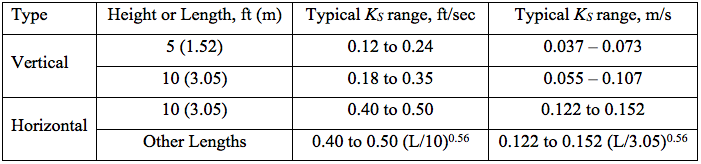
Per API 12J, “the maximum allowable superficial velocity, calculated form the above factors, is for separators normally having a wire mesh mist extractor. This rate should allow all liquid droplets larger than 10 microns to settle out of the gas. The maximum allowable superficial velocity or other design criteria should be considered for other type mist extractor. Mist extractor manufacturer’s recommended minimum distances upstream and downstream of the wire mesh between gas inlet and outlet nozzles should be provided for full utilization of the mist extractor. These values assume separators are equipped with standard mesh pad mist extractors” [7].
B. Campbell Book
The Ks method, Equation 2, is an empirical approach to estimate the maximum allowable gas velocity to achieve a desired droplet separation. For vertical separators with no mist extractor devices, Chap 11, Vol 2 of the Gas Conditioning and Processing book presents KS as a function of pressure and liquid droplet size [5]. This dependency of KS on pressure and droplet size is presented in Figure 2 [5]. Note for each droplet size a range of KS –values are given for a specified pressure.
For horizontal separators, the sizing depends on (in addition to the droplet size, density of gas and liquid phases, and gas velocity) separator effective length, Le, and the depth available for gas flow, hG, (i.e. liquid level) in the separators.
![Figure 2. KS as a function of pressure and liquid droplet size for vertical separators with no mist extractor devices [5]](http://www.jmcampbell.com/tip-of-the-month/wp-content/uploads/2015/08/fig2.png)
Figure 2. KS as a function of pressure and liquid droplet size for vertical separators with no mist extractor devices [5]
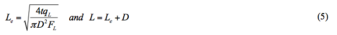
Sizing of the horizontal separators are more complicated. Referring to Figure 3, the effective Le may be defined in terms of separator actual length and diameter like Le=L-D. Therefore, the Souders-Brown parameter for horizontal separators, KSH, can be estimated in by Equation 4 in terms of KSV (read from Figure 2) for vertical separator [3].
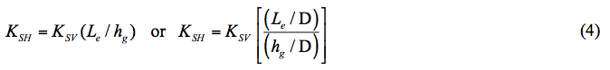
If the calculated value of KSH by Equation 4 is greater than the maximum value of 0.7 ft/sec (0.21 m/s), it should be set equal to this maximum value.
![Figure 3. Schematic of a horizontal gas-liquid separator [5]](http://www.jmcampbell.com/tip-of-the-month/wp-content/uploads/2015/08/fig3.png)
Figure 3. Schematic of a horizontal gas-liquid separator [5]
Where:
D = Diameter
FL = Fraction of cross section area occupied by liquid (function of liquid height in horizontal separator)
qL = Liquid actual volume flow rate
t = Residence time per API 12J [7]
If the calculated L/D is outside of its recommended range (normally 3 < L/D < 6), the liquid height in the vessel is changed and the calculations are repeated. For detail of calculations procedure refer to chapter 11 of reference [5].
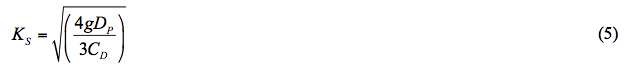
C. KS Correlations
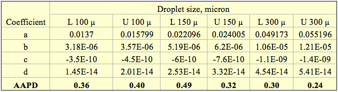
The curves for different droplet sizes shown in Figure 2 are fitted to a 3rd order polynomial (for droplet sizes of 100, 150, and 300 microns). The correlation is in the form of Equation 6 and its regressed coefficients a, b, c, and d are presented in Tables 2A and 2B for field (FPS) and System International (SI) units, respectively.
![]()
In Table 2, each droplet size in micron (µ) is preceded by letter L or U representing the lower and upper curve, respectively. The pressure is in psi and KS is in ft/sec for FPS (kPa and m/s in SI).
The last row of Table 2 provides the average absolute percent deviation (AAPD) of the predicted KS by the proposed correlation from the corresponding values of Figure 2 values.
Table 2A (FPS). Regressed coefficients for Equation 6 (P in psi and KS in ft/sec)
Droplet Size: 100 – 300 microns
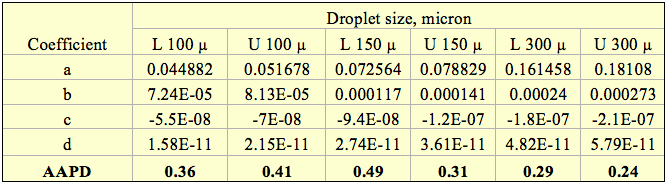
Table 2B (SI). Regressed coefficients for Equation 6 (P in kPa and KS in m/s in SI).
Droplet Size: 100 – 300 microns
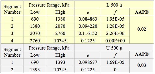
The two curves for 500 micron droplet size in Figure 2 were divided into 4 and 2 segments based on pressure range for the lower and upper curves, respectively. Each segment was fitted to a linear equation in the form of Equation 7 and its regressed coefficients e and f are presented in Tables 3A and 3B for FPS and SI units, respectively.
![]()
Table 3A (FPS). Regressed coefficients for Equation 7 (P in psi and KS in ft/sec)
Droplet Size: 500 microns
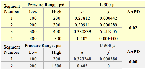
Table 3B (SI). Regressed coefficients for Equation 7 (P in kPa and KS in m/s in SI).
Droplet Size: 500 microns
D. Mist Extractors
The mist extractor is the final gas cleaning device in a conventional separator. The selection, and design to a large degree, determine the amount of liquid carryover remaining in the gas phase. The most common types include wire mesh pads (“mesh pads”), vane-type (vane “packs”) and axial flow demisting cyclones. Figure 4 shows the location and function of a typical mist extractor in a vertical separator.
Mist extractor capacity is defined by the gas velocity at which re-entrainment of the liquid collected in the device becomes appreciable. This is typically characterized by a KS –value, as shown in Equation 2. Mesh pads are the most common type of mist extractors used in vertical separator applications. The primary separation mechanism is liquid impingement onto the wires, followed by coalescence into droplets large enough to disengage from the mesh pad. References [1-5] provide mesh pad examples. Table 4 provides a summary of mesh pad characteristics and performance parameters.
![Figure 4. Typical mist extractor in a vertical separator [5]](http://www.jmcampbell.com/tip-of-the-month/wp-content/uploads/2015/08/fig4.png)
Figure 4. Typical mist extractor in a vertical separator [5]
Table 4. Mesh pads KS and performance parameters [3, 5, 8]
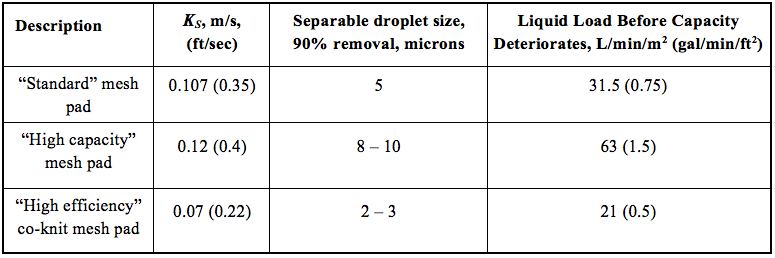
Notes:
- Flow direction is vertical (upflow).
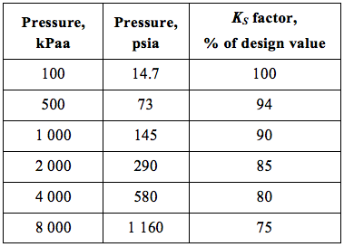
- Assume mesh pad KS – value decline with pressure as shown in Table 5. Table 5 was originally developed for mesh pads, but is used as an approximation for other mist extractor types. [9].
- If liquid loads reaching the mesh pad exceed the values given in Table 4, assume capacity (KS) decreases by 10% per 42 L/min/m2 (1 gal/min/ft2). [2-4].
- These parameters are approximate.
Table 5. Mesh pad KS deration factors as a function of pressure [5]
Vane packs, like mesh pads, capture droplets primarily by inertial impaction. The vane bend angles force the gas to change direction while the higher density liquid droplets tend to travel in a straight-line path, and impact the surface of the vane where they are collected and removed from the gas flow. Table 6 provides vane pack performance characteristics [3, 5, 8].
In the case of demisting cyclones, the vendor should be consulted in regards to performance for the current operations of interest.
Table 6. Typical vane-pack characteristics [3, 5, 8]
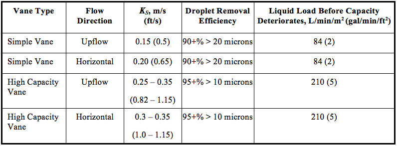
Notes:
- Assume vane-pack KS – value decline with pressure as shown in Table 5.
- If liquid loads reaching the vane pack exceed the values given in Table 2, assume capacity KS decreases by 10% per 42 L/min/m2 (1 gal/min/ft2). [2-4].
- These parameters are approximate only. The vane-pack manufacturer should be contacted for specific information.
Conclusions:
We focused on the application of Souders-Brown Approach (SBA) in gas-liquid separators and presented diagram, simple correlations and tables to estimate the SBA design parameter, KS.
- The SBA can provide reasonable results and is easy to use.
- The SBA is limited in that it is based on the average droplet size, but cannot quantify the amount of liquid droplets exiting the gas gravity section and mist extractor section.
- In a future TOTM we will discuss the droplet settling theory methods which can be used to more accurately quantify separator performance.
- Sizing of three-phase gas-liquid hydrocarbon-liquid water separators are more complicated and will be discussed in another TOTM.
To learn more about similar cases and how to minimize operational problems, we suggest attending our PF49 (Troubleshooting Oil and Gas Facilities), PF42 (Separation Equipment Selection and Sizing), G4 (Gas Conditioning and Processing), G5 (Gas Conditioning and Processing – Special), and PF4 (Oil Production and Processing Facilities), courses.
PetroSkills offers consulting expertise on this subject and many others. For more information about these services, visit our website at http://petroskills.com/consulting, or email us at consulting@PetroSkills.com.
Dr. Mahmood Moshfeghian
References:
- Snow–McGregor, K., http://www.jmcampbell.com/tip-of-the-month/2014/12/troubleshooting-gas-liquid-separators-removal-of-liquids-from-the-gas/
- Bothamley, M., “Gas-Liquid Separators – Quantifying Separation Performance Part 1,” SPE Oil and Gas Facilities, pp. 22 – 29, Aug. 2013.
- Bothamley, M., “Gas-Liquid Separators – Quantifying Separation Performance Part 2,” SPE Oil and Gas Facilities, pp. 35 – 47, Oct. 2013.
- Bothamley, M., “Gas-Liquid Separators – Quantifying Separation Performance Part 3,” SPE Oil and Gas Facilities, pp. 34 – 47, Dec. 2013.
- Campbell, J.M., Gas Conditioning and Processing, Volume 2: The Equipment Modules, 9th Edition, 2nd Printing, Editors Hubbard, R. and Snow–McGregor, K., Campbell Petroleum Series, Norman, Oklahoma, 2014.
- Souders, M. and Brown, G. G., “Design of Fractionating Columns-Entrainment and Capacity,” Industrial and Engineering Chemistry, Volume 26, Issue 1, p 98-103, 1934.
- American Petroleum Institute, 12J, Specification for Oil and Gas Separators, 8th Edition, October, 2008.
- PF-49, Troubleshooting Oil and Gas Processing Facilities, Bothamley, M., 2014, © PetroSkills, LLC. All Rights reserved.
- Fabian, P., Cusack, R., Hennessey, P., Neuman, M., “Demystifying the Selection of Mist Eliminators, Part 1: The Basics,” Chem Eng 11 (11), pp. 148 – 156, 1993.
Appendix
Derivation of the Souders-Brown and Stokes’ Law Equations
If we consider a spherical liquid droplet with a diameter of, DP, in the gas phase two forces as shown in Figure 1 act on it. The drag force, FD, is exerted by flow of gas and gravity force, FG, is exerted by weight of droplet. The drag force acts to entrain the liquid droplet while the gravity force acts to pull it down.
![Figure 1. Schematic of the forces acting on a liquid droplet in the gas phase [5]](http://www.jmcampbell.com/tip-of-the-month/wp-content/uploads/2015/08/appfig1.png)
Figure 1. Schematic of the forces acting on a liquid droplet in the gas phase [5]
At equilibrium, these two forces are equal.
![]()
The drag force is expressed as:
![]()
The droplet projected area, AP, is defined by:
![]()
The gravity force, FG, is defined
![]()
The volume of spherical droplet, VD, is calculated by
![]()
Substitution of Equations 3 and 4 into Equation 1 and solving for the gas maximum velocity,
For practical applications, the first term on the right hand side is replaced by KS
Therefore, the maximum gas velocity which prevents entrainment of liquid is obtained.
Equation 6 is called Souder-Brown equation and KS is referred to as the design parameter.
Where:
AP = Project area of droplet
CD = Drag coefficient
g = Acceleration of gravity
gC = Conversion factor
V = Gas velocity
VP = Volume of droplet
ρG = Gas density
ρL = Liquid density
Once the maximum, VGmax, gas velocity through the vessel is determined by Equation 6, one can calculate the required minimum cross sectional area of vessel for gas flow by the following equation.
![]()
Solving for the minimum vessel diameter, Dmin.
![]()
Where:
FG = Fraction of cross sectional area available for gas flow (FG = 1 for vertical separators and it is a function of liquid height for horizontal separators)
qa = Gas flow rate at the actual flowing condition
The drag coefficient, CD, is a function of Reynolds number, Re=(DPVρG)/µG. For Stokes’ law Re <≈2

Substitution of CD from Equation 9 into Equation 4 gives liquid droplet terminal velocity, VT, in the gas phase based on the Stokes’ law.

Similarly, the terminal velocity for the other flow regimes like Intermediate and Newton can be derived based on their corresponding expressions for the drag coefficients [3].

Very interesting article. Thank you very much
Please contact me to discuss a possible consulting project with your company regarding the design of gas-liquid separators
Thanks Sir, Its great article
You might want to look at the applications on my website. The software there does what is not available elsewhere. Especially for sizing horizontal separators. Access to the horizontal separator sizing is by subscription. But samples and a live version are available to use/view. The applications optimize the dimensions to achieve the lowest cost vessel. No guessing as to L/D.
This is a great discussion. It would be more useful if nozzle sizing were also included. Along with inlet devices.
Dear Sir,
It is a very interesting piece of information. Thanks a lot.
Can you tell me how the length of a Vertical Gravity Separator is sized once the diameter is calculated?
Thank you
really got to me.
What technique can I use to design a gas liquid separator for coupling analytical instruments like FI and AAS.
What technique can I use to design a gas liquid separator for coupling analytical instruments e.g HPLC and AAS
Possible typo in equation 5. I think there should not be the square root on the right hand side of equation 5.
You are correct, Ajay.
Thanks.
John,
This was a very helpful source for a class project. Thank you.
Vince Anderson, Iowa State ChE undergraduate
Hello: I have been asked whether it is important to maintain the size of a 16″ diameter horizontal knock out pot within the 3 < L/D < 6 range. Some folks want its length to be less than 4 feet. Do you have a response to this question? Thanks for your reply.
Not many details provided but here are some comments:
For this application length is mainly doing 2 things: 1) settling out larger droplets/entrainment ahead of the mist extractor (or gas outlet), 2) providing some distance to allow the gas velocity profile to straighten out, which helps with (1) and also should provide a more uniform velocity into the mist extractor (if used) preventing localized excessive velocities thru it.
If the inlet liquid load is low, (1) above may not be important if the mist extractor can handle the liquid. If the horizontal gas velocity profile is expected to be fairly uniform (would need more details to determine this) then (2) might not be a concern either.
Length could also be providing “residence time” for collected liquid but this probably isn’t a concern for a “knock-out pot”.
Mark Bothamley