This tip is the follow up of the previous tips (April and May 2016) [1-2], which investigated the benefits of having a water-draw and its optimum location in a condensate stabilizer column [see chapter 16 of reference 3]. It will simulate the performance of an operating condensate stabilizer column equipped with side water-draw tray to remove liquid water. Recall from the April 2016 TOTM, water can become trapped internally within a condensate stabilizer. The column operating conditions result in water condensing within the column and becoming trapped. The overhead temperature is too cool and the bottoms temperature is too hot to allow the water to leave the column in either of the product streams. As a result, liquid water build-up will occur within the column reducing capacity, and depending upon composition, increasing corrosion. Eventually the water build-up will cause the column to flood, and the major disruption in the tower operations allows the water to be removed. After this event, the column will operate normally until sufficient time that enough water has accumulated to cause the column to flood once again. A properly located water-draw off tray will allow for proper column operation and eliminate the operating problems associated with water build up.
In this case study, a stripping sweet gas stream is also utilized to achieve low H2S content and stabilized condensate at a specified reboiler temperature. The tip will perform three-phase (vapor, liquid hydrocarbon, and aqueous phases) calculations on the trays with excessive/free water rates. Specifically, it will study possible locations of a water-draw tray based on the profiles for water partial pressure in the vapor phase and water rates in the light and heavy liquid phases. The tip will present a summary of the computer simulation results and the key diagrams for the same plant.
Case Study:
Table 1 presents the raw condensate and stripping gas compositions, rates and conditions. Figure 1 presents a simplified process flow diagram equipped with stripping gas and water-draw tray for stabilization of a raw condensate. The 3-phase separator upstream of the stabilizer column removes essentially all excess/free water. The tip utilizes the front mixer to recombine the light and heavy liquid (excess free water) streams feeding to the column for the simulation purpose only. Table 2 presents the stabilizer column specifications. While location of the water-draw tray is 7 in this figure, the tip also considered tray locations at 5, 8, 9, 17, and 18.
The stripping sweet gas stream lowers the H2S content of the stabilized oil and achieves the desired condensate vapor pressure at the specified reboiler temperature. Table 2 presents the specified column variables. Stream 2 is the overhead vapor and stream 3 is the stabilized condensate.
Based on the data in Tables 1 and 2, and the process flow diagram of Figure 1, the tip performed simulation using the Soave-Redlich-Kwong (SRK) equation of state [4] in ProMax [5] software.

Table 1. Feed and stripping gas compositions, rates and conditions

Figure 1. A simplified non-refluxed stabilizer column with side water-draw and stripping gas

Table 2. Condensate stabilizer column specifications
Simulation Results:
The tip varied the boil-up ratio in the reboiler to match the stream 3 plant temperature of 482 °F (250 °C). The resulting boil up-ratio of 76.5 % is presented in Table 2 and Table 3 presents the comparison between simulation results of this work with plant data. Overall, a reasonable agreement is observed.

Table 3. Comparison of simulation results with plant data
Figure 2 presents the water partial pressure profile for cases of no water-draw and water-draw at either tray of 7, 8 or 9. In this figure, a large spike of water partial pressure is observed on tray 18 for the cases of no water-draw tray. For the case of no water-draw, a bump in water partial pressure is also observed at tray 10 due to the presence of water in the stripping gas that enter the column on tray 10.
Similarly Figures 3 and 4 present the water rate profiles in the light (liquid hydrocarbon) and heavy liquid (aqueous) phases, respectively. These figures show the water rate profiles for no water-draw and water-draw tray at either tray 7, 8, or 9. In these figures, a large spike of water rate profile is observed for the case of no water-draw tray.
Figure 4 indicates that below any of the water-draw trays the light (hydrocarbon) liquid phase is under-saturated with water and there is no free water (heavy liquid phase). For the case of no water-draw, the light liquid phase remains saturated with water along trays 1 through 18.
Figure 5 indicates that the presence of a water-draw tray has no significant impact on the column temperature profile.
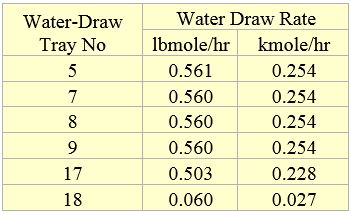
In all cases the location of a water-draw tray has no impact on Reid Vapor Pressure (RVP) of neither condensate nor the reboiler duty. The calculated RVP for all cases was 8.2 psi (56.6 kPa) and the calculated reboiler duty for all cases was 18.378 MMBtu/hr (5.376 MW). Table 4 presents the impact of water-draw location on the rate of water removed. This table indicates that water rate at either trays of 5 through 9 practically is the same amount.

Figure 2. Water partial pressure profile in the stabilizer column for several cases

Figure 3. Water rate in light liquid phase in the stabilizer column for several cases

Figure 4. Water rate in heavy liquid phase in the stabilizer column for several cases

Figure 5. Temperature profiles in the stabilizer column for several cases
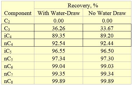
Table 5 presents the percent recovery (ratio of a component rate in the condensate to its rate in the feed stream) of selected components in the stabilized condensate. Practically, all ethane and lighter components (N2, C1, CO2, and H2S) leave in the column overhead. Table 5 indicates that the presence of a water-draw tray has some effect on propane and little effect on butane but no effect on other component recoveries.

Table 4. Impact of water-draw tray location on removal water rate

Table 5. Recovery of selected components in the stabilized condensate
Conclusions:
The tip investigated the location of side water-draw and its impact on the performance of the stabilization column. Based on the results obtained, this tip presents the following observations.
- The water-draw rate at either trays 5 through 9 is the same.
- The water draw tray location had no impact on the RVP of stabilized condensate.
- The water draw tray location had no impact on the reboiler duty.
- The water draw try improved the propane recovery.
To learn more about similar cases and how to minimize operational problems, we suggest attending our G4 (Gas Conditioning and Processing), G5 (Advanced Applications in Gas Processing), and PF4 (Oil Production and Processing Facilities), courses.
PetroSkills offers consulting expertise on this subject and many others. For more information about these services, visit our website at http://petroskills.com/consulting, or email us at consulting@PetroSkills.com.
By: Dr. Mahmood Moshfeghian
Reference:
- Moshfeghian, M., April 2016 tip of the month, PetroSkills | John M. Campbell, 2016.
- Moshfeghian, M., May 2016 tip of the month, PetroSkills | John M. Campbell, 2016.
- Campbell, J.M., Gas Conditioning and Processing, Volume 2: The Equipment Modules, 9th Edition, 2nd Printing, Editors Hubbard, R. and Snow–McGregor, K., Campbell Petroleum Series, Norman, Oklahoma, 2014.
- Soave, G., Chem. Eng. Sci. 27, 1197-1203, 1972.
ProMax 4.0, Bryan Research and Engineering, Inc., Bryan, Texas, 2016.
