In this Tip of The Month (TOTM), regeneration of rich triethylene glycol (TEG) with striping gas at high pressure is investigated. Specifically, this study focusses on the determination of the required stripping gas rate as a function of the lean TEG mass percent, reboiler temperature, and the number of theoretical trays in the stripping section (NS) for a regenerator (still) column with two theoretical trays (NR). By performing rigorous computer simulations of TEG regeneration at high pressure, a series of charts for quick determination of stripping gas rates needed for facilities type calculations are developed. The results of this study are also compared with the case of TEG regeneration at atmospheric pressure, which was published in the June 2013 TOTM.
In gas dehydration service, TEG absorbs limited quantities of benzene, toluene, ethylbenzene, and xylene ( BTEX) along with other volatile organic compounds (VOCs) from the gas. BTEX and other VOC emissions are an environmental challenge for the natural gas industry since some of these compounds are considered to be carcinogenic.
Absorption is favored at lower temperatures, higher pressure, increased lean TEG concentration and circulation rate. Based on the data from the June 2011 TOTM [1], predicted absorption levels for BTEX components vary from 5 to 15% for benzene, 5 to 25% for toluene and ethylbenzene, and 5 to 35% for xylene [2]. Some of these absorbed BTEX components are released with the flashed gas off of the TEG separator operating at around 483 kPag (70 psig). The flashed gas may be used as fuel or sent to the flare. The rich TEG solution is normally regenerated at low pressure and high temperature. The remaining BETX components are released with the vaporized water and stripping gas at the top of the still column. Hicks et al. [3] discuss different options for VOC emission control. One of their options was to operate the reboiler at pressures that allow the overhead vapors that contain VOCs including BTEX and stripping gas to flow directly to either compressor suction, a fuel system, or to a flare. Their study showed higher pressure reboilers effectively control BTEX emissions and economically recover all the hydrocarbon vapors with minimal incremental capital cost and no required emissions monitoring. Hicks et al. [3] highlighted the following advantages for the pressurized glycol regeneration system:
- All vapors (VOCs, H2S, CO2) released from the glycol are at a sufficient pressure, which allows the use of simple handling methods without discharge to the atmosphere. Typical handling methods are:
- Mixing the released vapors with fuel gas or other gas users.
- Using compressors in other service instead of dedicated compression to recompress the released vapors.
- Using dedicated compression which allows for better reboiler pressure operation.
- Because the previously mentioned methods can handle vapors from the still overheads, one can eliminate the equipment specifically designed to recover these vapors. This equipment typically includes condensers, separators, pumps, and a means for burning or incinerating the non-condensable vapors. The entire still column overhead can be routed to the compression suction scrubbers with no intervening components like a condenser or separator.
- The larger-than-normal amount of stripping gas used in the stripper results in less VOCs in the condensed water vapor from the overheads. This is because the vapor-liquid equilibrium is shifted such that condensation of VOCs is minimized. The disposal water will therefore contain significantly less undesirable components. Similarly, for those systems in which the overheads are mixed with other gases, the volume ratio of overhead to mixing gas (such as gases for fuel and compressor suction) will further reduce the VOCs in the condensed water.
- No environmental testing for atmospheric discharge of VOCs is required because no VOCs will be released, as is often the case with conventional technology. Furthermore, discharge of VOCs from the regeneration system at considerably higher-than-normal pressures facilitates mixing and extreme dilution of VOCs in plant fuel or in fuel sold and transmitted to remote users.
Computer Simulation Results:
In order to study the impact of stripping gas rate on the lean TEG mass percent, the TEG regeneration process was simulated using ProMax [4] software with its Soave-Redlich-Kwong (SRK) [5] equation of state (EOS). The process flow diagram used for these simulations is shown in Figure 1.

Figure 1. Sample results using ProMax [3] for high pressure TEG regeneration at reboiler P=515 kPaa (74.7 psia) and NS=2
As shown in Figure 1, the rich TEG solution contained 97.5 mass percent TEG entering the still column at 150°C (302°F) and 515 kPaa (74.7 psia). The reboiler temperature was set at 204°C (400°F) and boil-up ratio of 0.1 (molar bases). Two theoretical trays in the still column (NR = 2) and two theoretical trays (NS = 2) in the gas striping section were specified. The striping gas enters the bottom of the gas stripping section at 150°C (302°F) and 521.9 kPaa (75.7 psia). Methane was used for the stripping gas at a rate of 70 std m3/h (2458 scf/hr). The regenerated lean solution contains 99.25 mass percent TEG and the ratio of stripping gas to lean TEG liquid volume rates is 80.26 std m3 of gas/std m3 of lean TEG solution (10.73 scf/sgal). If stripping gas was sparged directly into the reboiler (NS = 0, no gas stripping section), with everything else remaining the same, the regenerated solution contains 98.49 mass percent TEG and the ratio of stripping gas to lean TEG liquid volume rates is 79.58 std m3 of gas/std m3 of lean TEG solution (10.64 scf/sgal). For the above cases the number of theoretical trays in the still column is increased from 2 to 3 (NR = 3) and the lean TEG concentration remained almost the same. The concentration of rich TEG solution is also varied from 90 to 98 mass percent, but no appreciable change in the lean TEG concentration was observed for the same stripping gas rate.
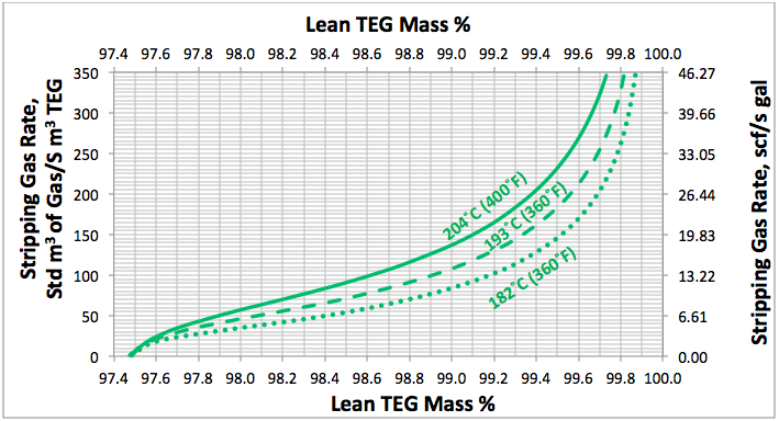
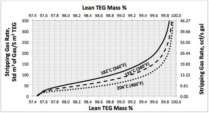
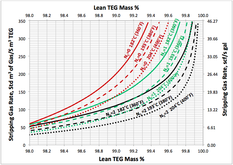
Using a similar set up as is shown in Figure 1, several simulations were performed for; a range of stripping gas rates, for NR=2, NS=0, 1, 2 and for reboiler temperatures of 204, 193, and 182°C (400, 380, and 360°F) and a reboiler pressure of 515 kPaa (74.7 psig). The results of these simulation runs are presented in Figures 2 to 4. For purposes of comparison all of these diagrams are replotted in Figure 5.

Fig 2. Effect of lean TEG mass %, reboiler temperature and number of theoretical trays in stripping gas column (NS=0) at reboiler P=515 kPaa (74.7 psia) on the stripping gas rate

Fig 3. Effect of lean TEG mass %, reboiler temperature and number of theoretical trays in stripping gas column (NS=1) at reboiler P=515 kPaa (74.7 psia) on the stripping gas rate

Fig 4. Effect of lean TEG mass %, reboiler temperature and number of theoretical trays in stripping gas column (NS=2) at reboiler P=515 kPaa (74.7 psia) on the stripping gas rate
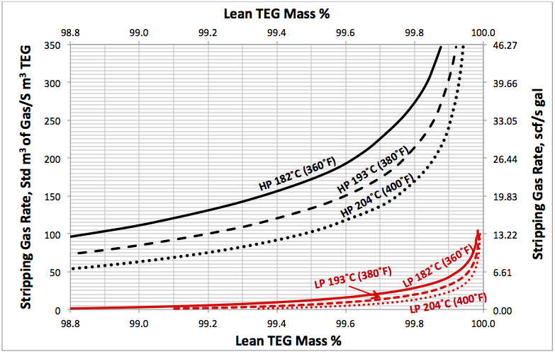
Figure 6 presents the required stripping gas rate for both a pressurized reboiler, 515 kPaa (74.7 psia), and a low pressure, 109 kPaa (15.8 psia) reboiler having two theoretical trays (NS=2) in the gas stripping section. This figure indicates that required stripping gas rates are 10 to 100 times higher for pressurized reboiler when compared to the low pressure reboiler.
Conclusions:
In this TOTM, the effect of stripping gas rate on the regenerated lean TEG concentration at high pressure for several operation conditions was studied. A series of charts to use for a quick determination of the required stripping gas rate to achieve a desired level of lean TEG concentration are presented in Figures 2 through 6. These charts are based on the rigorous calculations performed by computer simulations and can be used for facilities type calculations for evaluation and trouble shooting an operating TEG dehydration unit. In addition, the following observations were made:
- For rich TEG concentrations between 90 and 98 mass percent, the required stripping gas rate is independent of rich TEG concentration.
- As the number of theoretical trays in the stripping column (NS) increases from 0 to 2, the required striping gas rate decreases.
- Increasing the number of theoretical trays in the still column (NR) from 2 to 3 has no appreciable effect on the stripping gas requirement.
- Increasing the reboiler temperature from 182 to 204 °C (360 to 400 °F), decreases the required stripping gas rate.
- Increasing the TEG reboiler pressure from 109 kPaa (15.8 psia) to 515 kPaa (74.7 psia) increases the stripping gas requirement by a factor of between 10 and 100 depending on other factors.

Fig 5. Effect of lean TEG mass %, reboiler temperature and number of ideal trays in stripping gas column on the stripping gas requirement at reboiler P=515 kPaa (74.7 psia).
To learn more, we suggest attending our G40 (Process/Facility Fundamentals), G4 (Gas Conditioning and Processing), G5 (Gas Conditioning and Processing-Special), and PF81 (CO2 Surface Facilities), PF4 (Oil Production and Processing Facilities), courses.
John M. Campbell Consulting (JMCC) offers consulting expertise on this subject and many others. For more information about the services JMCC provides, visit our website at www.jmcampbellconsulting.com, or email us at consulting@jmcampbell.com.
By: Dr. Mahmood Moshfeghian

Fig 6. Comparison of high pressure with low pressure stripping gas requirements for TEG regeneration. HP=515 kPaa (74.7 psia), LP=109 kPaa (15.8 psia) with NS=2
References:
- Moshfeghian, M., http://www.jmcampbell.com/tip-of-the-month/2011/06/absorption-of-aromatics-compounds-in-teg-dehydration-process/, Tip of the Month, June 2011.
- Moshfeghian, M. and R.A. Hubbard, “Quick Estimation of Absorption of Aromatics Compounds (BTEX) in TEG Dehydration Process,” Proceedngs of the 3rd International Gas Processing Symposium, March 5 – 7 2012 , Qatar , 2012.
- Hicks, R., Gallaher, D. and R. Craig, “Pressurized reboiler reduces VOC emissions in glycol dehy systems”, Oil & gas j., Vol 102, Issue 17, April 2004.
- ProMax 3.2, Bryan Research and Engineering, Inc., Bryan, Texas, 2013.
- Soave, G., Chem. Eng. Sci. Vol. 27, No. 6, p. 1197, 1972.

TEG has a degradation temperature of 207ºC (which is why the reboiler is limited to 204ºC). My question concerns whether increased pressure has any effect on the degrdation temperature?
Has anyone done any research or have any data on the effect of pressure on the degradation temperature of TEG?
Most TEG regenerators operate at atmospheric, so feedback may be limited.
An impressive share! I’ve just forwarded this
onto a colleague who had been conducting a little homework on
this. And he in fact bought me lunch simply because I found it for him…
lol. So allow me to reword this…. Thanks for the
meal!! But yeah, thanx for spending some time to discuss this topic here on your blog.
Thanks for an interesting and useful set of correlations on TEG regeneration at elevated pressure 🙂
When studying the graphs, I suspect that the temperature curves on Fig.3 have mistakenly been inversed.
Bonjour Dr. Mahmood,
C’est par hasard que j’ai consulté votre site qui ma vraiment impressionner, il est très bénéfique et on a beaucoup de choses a apprendre. Veuillez accepter monsieur le docteur tous mes remerciements.
Mon souci est comme suite:
La ou je travaille, on a des rebouilleurs pour régénération de TEG et on a eu toujours une instabilité des niveaux suite aux excès de vapeurs et condensations dans ces rebouilleurs. (Sachant que nos transmetteurs de niveaux fonctionnent à base de ΔP
Est ce que l’utilisation de streaming gas peut remédier ce problème sans effets négatifs bien sur.
Salutations.
Ahmed
When I initially commented I appear to have clicked on the -Notify me
when new comments aree added- checkbox and from
now on each time a comment is added I get four emails
with the same comment. There has to be a way you can remove me from
that service? Many thanks!