Guidelines for Liquid Density Prediction – Part 1: Correlations

In the previous “Tip of the Month” we briefly discussed the importance of liquid density for process simulation and equipment design and introduced different methods of their predictions. In addition to direct laboratory measurement, three different methods were introduced to compute liquid density. The methods were (a) charts and monographs, (b) correlations and (c) EoS or volume translated EoS.

In this “Tip of the Month”, we will present a comparison between accuracy of different correlations and EoS methods. The focus will be on correlations for light hydrocarbons which have wider applications in industry.

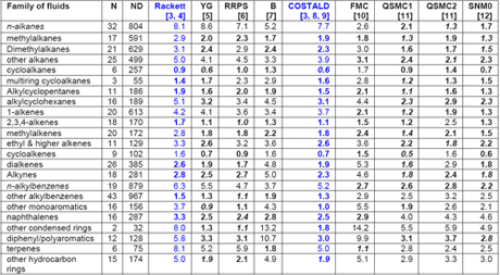
Recently, Mulero et al. [1] have evaluated nine empirical correlations for their accuracy and applicability in calculation of the liquid saturation density of pure fluids. All of them were based on the corresponding states principle, and they have included very recent correlations. One model required only the knowledge of critical parameters, but most of them needed the critical parameters and acentric factor as inputs, and one required the Lennard-Jones molecular parameters and the acentric factor as input data. As a reference, they took the numerical values for the liquid saturation density accepted by the DIPPR [2] project for 552 fluids, grouped into 30 families. Recommendations are given for the use of each model and for the choice of the adequate model for each family of fluids, including for particular fluids. For detail comparison and suggestions, the readers are referred to their paper; however, Table 1 is a summary of their comparison for pure fluids. The two most common correlations in gas industry, Rackett and COSTALD (highlighted in blue color) are also discussed in Chapter 3 of JMC Volume 1 of Gas Conditioning and Processing Book [3].

Table 1: MAPDs (Mean value of Absolute Percent Deviations) of the Calculated Liquid Saturation Densities for Several Families of Fluids with Respect to the DIPPR [2] Data when Using Correlationsa-c [1]

Chart 1

The numbers in italics represent the lowest MAPDs, and the numbers in bold show MAPDs that are similar (1%) to the lowest one. b YG) Yamada and Gunn; RRPS ) Reid et al.; B) Bhirud; QSMC1) Queimada et al.; QSMC2) Queimada et al.; SNM0) Mchaweh et al.; FMC) Fau´ndez et al.. c N) number of fluids, ND) number of data.

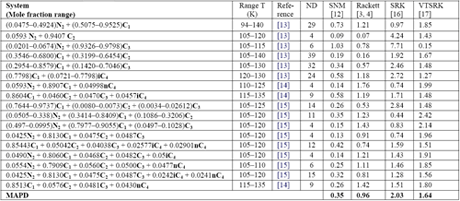
Similarly, Mchaweh et al. [12] reported the results of comparison study for light hydrocarbon mixtures containing nitrogen. A summary of their work is presented in Table 2. Their evaluation did not include COSALD; however, our experience indicates that COSTALD MAPD is below 0.5 %. It should be noted that even though Volume Translated SRK (VTSRK) improves the accuracy of the SRK EoS but still is not good enough for industrial applications.

Table 2: The MAPD for 17 multi-component low temperature systems (226 data points) using different method [12]

Chart 2

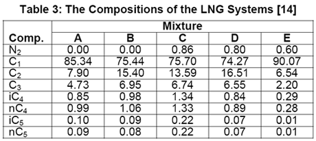
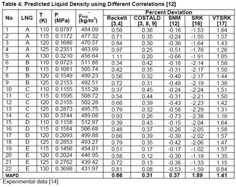
In another paper, Javanmardi et al. [18] evaluated several correlations and EoSs for prediction of LNG density. Among others, five LNG mixtures consisting of 22 experimental data were studied. The compositions of these LNG mixtures are presented in Table 3 and a summary of comparison between accuracies of different methods is shown in Table 4.

Table 3

Analysis of Tables 1 through 4 indicates that, for pure compounds, the SNM [12] in general gives better accuracies. However, for light hydrocarbon mixtures (NGL and LNG) liquid densities prediction, it is highly recommended to use COSTALD [3, 8, 9] even though SNM correlation also give accurate and compatible results. The SRK [16] and its volume translated correction (VTSRK, [17]) accuracies are not as good as the correlations so their use for practical applications must be done with care and caution. Needless to point out that SRK predict gas densities accurately. Based on our experiences and similar observations, we have programmed, in the JMC GCAP software, SRK for gas and COSTALD for liquid densities.

Table 4

In next “Tip of the Month” we will provide Part 2 of guidelines for proper use of commercial simulator to calculate liquid densities.

To learn more about liquid density and its impact on facilities calculation, design and surveillance, refer to JMC books and enroll in our G4 (Gas Conditioning and Processing) and G5 (Gas Conditioning and Processing – Special) courses.

By Dr. Mahmood Moshfeghian

Reference:

  1. Mulero, A., Cachadina, I. and Parra, M. I., “Liquid Saturation Density from Predictive Correlations Based on the Corresponding States Principle. Part 1: Results for 30 Families of Fluids,” Ind. Eng. Chem. Res., 45, 1840-1848, 2006
  2. DIPPR (Design Institute for Physical Property Data) files, Version 17.0; American Institute of Chemical Engineers: New York, 2003 (supplied by Technical Database Services, Inc., www.tds.cc).
  3. Campbell, J. M. “Gas conditioning and processing, Volume 1: Fundamentals,” John M. Campbell and Company, Norman, Oklahoma, USA, 2001.
  4. Rackett, H. G. Equation of state for saturated liquids. J. Chem. Eng. Data, 15, 514, 1970 5. Yamada, T.; Gunn, R. D. Saturated liquid molar volumes: The Racket equation. J. Chem. Eng. Data, 18, 234, 1973
  5. Reid, R. C.; Prausnitz, J. M.; Sherwood, T. K. The Properties of Gases and Liquids; McGraw-Hill: New York, 1977.
  6. Bhirud, V. L. A four-parameter corresponding states theory: Saturated liquid densities of anormal fluids. AIChE J., 24, 1127, 1978.
  7. Hankinson, R. W.; Thomson, G. H. A new correlation for saturated densities of liquids and their mixtures. AIChE J. 1979, 25, 653.
  8. Thomson, G. H.; Brobst, K. R.; Hankinson, R. W. An improved correlation for densities of compressed liquids and liquid mixtures. AIChE J., 28, 671, 1982
  9. Faundez, C. A.; Mulero, A.; Cuadros, F. Molecular Thermodynamic Models for the Vapour-Liquids Equilibrium of Non-Polar Fluids. J.. Phase Equilib., 21, 364, 2000.
  10. Queimada, A. J.; Stenby, E. H.; Marrucho, I. M.; Coutinho, J. A. P. A new corresponding states model for the estimation of thermophysical properties of long chain n-alkanes. Fluid Phase Equilib., 212, 303, 2003.
  11. Mchaweh, A.; Alsaygh, A.; Nasrifar, Kh.; Moshfeghian, M. A simplified method for calculating saturated liquid densities. Fluid Phase Equilib., 224, 157, 2004.
  12. M.J. Hiza, W.M. Haynes, W.R. Parrish, J. Chem. Thermodyn. 9, 873–896, 1977.
  13. Haynes, W. M., Measurements of Orthobaric-Liquid Densities of Multicomponent Mixtures of LNG components Between 110 and 130 K, J. Chem. Thermodynamics, 14, 603-612, 1982.
  14. M.J. Hiza, W.M. Haynes, J. Chem. Thermodyn. 1, 1–10, 1980.
  15. Soave, G., Chem. Eng. Sci., vol. 27, 1197-1203, 1972.
  16. Peneloux, A. E., Rauzy, E., and Freze, R., Fluid Phase Equilib., Vol. 8, 7-23, 1982.
  17. Javanmardi, J., Nasrifar, Kh., Moshfeghian, M., Comparing different methods for prediction of liquefied natural gas densities, Engineering Journal of the University of Qatar, Vol. 18, 39-56, 2005

1 response to “Guidelines for Liquid Density Prediction – Part 1: Correlations”

  1. Agne Myhre says:

    Hello,

    If i want to calculate the density (liquid) of ethane. Beetween – 70 to -100 degC. How do i proceed?

    Thanks in advance.

    Agne Myhre

Liquid Density

Liquid density is needed for process simulation and equipment design. For example, accurate predictions of liquid density are needed for calculation of pressure drop in a piping/pipeline and vessel sizing. Accurate liquid density is also essential for custody transfer.

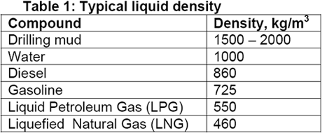
Liquid density ranges from a few hundred above thousand to couple of 100 kg/m3. Table 1 presents typical range of liquid densities where as typical re-injection gas has a density in the range of 125 to 150 kg/m3 and pipeline gases at 7000kPa has a density in the order of 70 kg/m3.

Chart 1

Liquid densities are sometime expressed in terms of relative density (specific gravity) or API gravity. The relative density,? , is defined as:

Equation 1

and the API (American Petroleum Index) gravity is:

Equation 2

Depending on the applications, three different methods can be used to compute liquid density in addition to direct laboratory measurement. These methods are (a) charts and monographs, (b) correlations and (c) EoS or volume translated EoS, of which the correlations are usually the most accurate.

For the LNG density measurement and calculation, one of the standard procedures practiced in industry is ISO 6578: 1991 [1]. This procedure specifies the calculations to be made to adjust the volume of a liquid from the conditions at measurement to the equivalent volume of liquid or vapor at a standard temperature and pressure, or to the equivalent mass or energy (calorific content). Annexes A to H of this procedure form an integral part of this standard.

Generalized Charts

There are several generalized charts for prediction of liquid density of petroleum fluids and hydrocarbons [2].

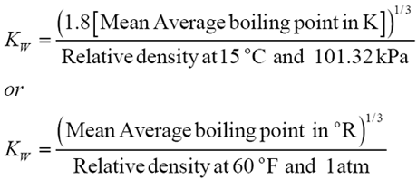
The relative density of petroleum fluids are normally expressed in terms of two of three characteristics- API gravity at 15°C, the Watson characterization factor, KW, or the mean average boiling point. The Watson characterization factor is defined in terms of mean average boiling point, Tb, and the relative density at standard condition.

Equations 3 and 4

The charts normally present the relative density of paraffinic hydrocarbon mixtures at their boiling point or bubble point temperature and pressure. These charts apply to mixtures as well to pure components. Alignment points for paraffinic hydrocarbon mixtures and pure components are located according to their molecular weight. The accuracy of these charts is generally within 3 % of the measured values. However, the accuracy is somewhat less for mixtures having molecular weights less than 30 where temperature is low, and where the methane content is high or reduced temperatures above 0.9 [3].

EoS Methods and Volume Translation

The EoSs are used in commercial simulation softwares for predicting phase behavior and thermodynamic properties. Generally, EoSs need a few parameters (usually two or three) that are normally obtained from critical properties. The cubic equations of state (EOS) give accurate results for prediction of vapor-liquid equilibria, especially for non-polar or slightly polar systems. Furthermore, these equations could be used to accurately predict vapor densities, enthalpy and entropy. These advantages encourage the researchers to augment EoS ability more than before, especially, liquid density, although their accuracy for liquid density prediction is not as good as correlations. The popular EoSs such as SRK [4] and PR [5] predict liquid density with an average absolute error about 8%, much more than the correlations [6]. This large magnitude of error is not acceptable by industry; therefore; they are not used for this purpose. In order to overcome this deficiency, a volume translated method has been developed by Peneloux et al. [7]. The working equations are:

Equation 5

In the above equation, vSRK is calculated by SRK EoS and the correction term “c” as follows:

Equation 6

Correlations

In order to calculate liquid density reliably, several correlations such as COrresponding STAte Liquid Density (COSTALD) and modified Rackett equation by Spencer and Danner (RSD), have been developed.

COSTALD correlation: The COSTALD correlation, Hankinson and Thomson [8], requires two parameters, ?SRK, the optimized value of the acentric factor based on the SRK EoS and V*, the pure component characteristic volume.

The RSD correlation: Spencer and Danner [9] improved the liquid density correlation of Rackett [10]. The improved correlation for saturated liquid density calculation requires only ZRA, the improved compressibility factor.

In next “Tip of the Month” we will provide guidelines for use of these methods and present the results of a comparison study between these methods.

To learn more about liquid density and its impact on facilities calculation, design and surveillance, refer to JMC books and enroll in our G4 (Gas Conditioning and Processing) and G5 (Gas Conditioning and Processing – Special) courses.

By Dr. Mahmood Moshfeghian

Reference:

  1. http://www.iso.org
  2. Campbell, J. M. “Gas conditioning and processing, Volume 1: Fundamentals,” John M. Campbell and Company, Norman, Oklahoma, USA, 2001.
  3. Engineering Data Book, 10th and 11th Editions, Gas Processors and Suppliers Association Data Book, Tulsa, Oklahoma, 1998.
  4. Soave, G., Chem. Eng. Sci., vol. 27, pp. 1197-1203, 1972.
  5. Peng, D. Y., and Robinson, D. B., Ind. Eng. Chem. Fundam., vol. 15, p. 59, 1976.
  6. Nasrifar, Kh. and M. Moshfeghian, J. of Fluid Phase Equilibria, 158-160, pp. 437-445, 1998.
  7. Peneloux, A. E., Rauzy, E., and Freze, R., Fluid Phase Equilib., vol. 8, pp. 7-23, 1982
  8. Hankinson, R. W., Thomson, G. H., AIChE J., vol. 25, no. 4, pp. 653-663, 1979.
  9. Spancer, C. F., and Danner, R. P., J. Chem. Eng. Data, vol. 17, no. 2, pp. 236-241, 1972.
  10. Rackett, H. G., J. Chem. Eng. Data, vol. 15, no. 4, pp. 514-517, 1970.

1 response to “Liquid Density”

  1. Howdy very nice blog!! Guy .. Excellent .. Amazing .. I’ll bookmark your blog and take the feeds additionally…I’m glad to seek out a lot of useful info right here in the post, we need develop more strategies in this regard, thank you for sharing.

Guidelines for Selecting K-Value Method

In the previous “Tip of the Month”, we presented several methods for estimating Kvalues. The methods presented were the GPA correlations and charts, Raoult’s law, Wilson’s correlation, EoS approaches, activity coefficient models and JMC Charts and Tables. However, the question arises as to which equation or method should be used? The answer to this question “depends” on many factors such as pressure, temperature, composition, and components of the system.

In this “Tip of the Month” we will provide guidelines for use of these methods and present the results of a comparison study between these methods.

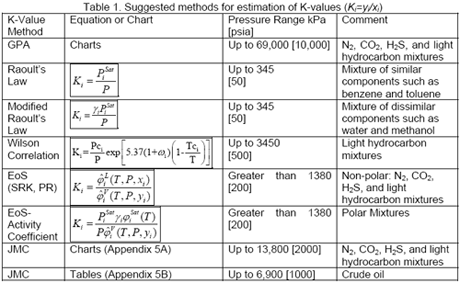
Table 1 presents the list of suggested methods for estimation of K-values and the applicable pressure range.

Chart 1

Comparison of methods:

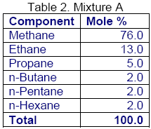
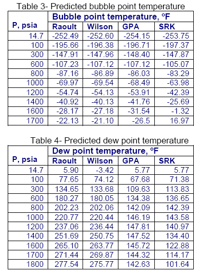
For mixture A shown in Table 2, a series of bubble pointand dewpoint calculations were performed using Raoult’s law, Wilson correlation, GPA charts, and the SRK EoS. The summary of results is shown in tables 3 and 4, respectively.

Chart 2

As can be seen from Table 3 and 4, at low pressures, all of the methods produce very close answers; however, as the pressure increases they deviates considerably from each other.

In general Raoul’t law and Wilson correlation generates close answers. The GPA and SRK results are close to each other up to 1000 psia. However, at higher pressures they deviate from each other. As can be seen by this comparison, it is important to not apply these K-value equations outside of their recommended range of application.

It can also be seen that even when the equations are applied properly widely varying results can be obtained as is the case with the GPA and SRK results. In order to determine which equation is providing the most accurate results it is a good idea to compare the results with actual data. Experimental data may also be used to tune (improve the accuracy) of a correlation or an EoS.

Charts 3 and 4

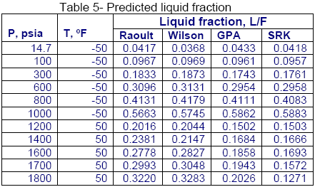
Similarly, for the same mixture shown in Table 1, a series of flash calculations for two isotherms were performed and the calculated liquid fractions (L/F) using different methods are compared in Table 5. Again, the calculated liquid fractions by the Raoult’s law and Wilson correlations are close to each other but they deviate considerably from the GPA charts and the SRK EoS results.

Guidelines:

Due to the observation made in the previous section and other studies, care must be taken in selecting K-values correlations. Therefore, the following guidelines extracted from page 128 of Vol 1 of JMC book are suggested.

The accuracy of the results of calculations involving K-Values depends on the reliability of sampling, of the analysis of that sample, and the K-Value correlation used.

There is no single K-Value correlation that is superior for all mixtures encountered. An experienced practitioner may have two or three different models or program available. Generally, crude oil and NGL phase behavior is handled by different models.

Chart 5

All K-values are sensitive to composition, particularly the very volatile components like nitrogen, methane, and ethane.

For design purposes, several models may be used to determine a range of results. This range, rather than one set of “magic” numbers, is then used to size equipment. The name of the game is flexibility. It is doubtful if one ever will encounter the analyses, flow rates and exact other conditions used as the design basis.

It is most important that the K-values be internally consistent. There are several methods available for this purpose (See pages 113-116 of Vol 1 of JMC Books).

An experienced practitioner usually can predict the quantity of a specified liquid within 6% (for a specified analysis and conditions). The compositional analysis on which the calculation was based will often be in error more than this. This is important, for in many systems a series of VLE calculations is made; the output from one is the input to another. The errors thus accumulate. Many less than desirable systems results from failure to recognize this.

To learn more on applications of K-values and their impact on facilities calculation, design and surveillance, refer to JMC books [1-3] and enroll in our G4 (Gas Conditioning and Processing) and G5 (Gas Conditioning and Processing – Special) courses.

By Dr. Mahmood Moshfeghian

Reference:

  1. Maddox, R. N. and L. L. Lilly, “Gas conditioning and processing, Volume 3: Advanced Techniques and Applications,” John M. Campbell and Company, Norman, Oklahoma, USA, 1994.
  2. Campbell, J. M. “Gas conditioning and processing, Volume 1: Fundamentals,” John M. Campbell and Company, Norman, Oklahoma, USA, 2001.
  3. Campbell, J. M., “Gas conditioning and processing, Volume 2: Equipment Modules,” John M. Campbell and Company, Norman, Oklahoma, USA, 2001.

Nomenclature:

Ki – Vapor–liquid equilibrium ratio
P – Pressure, kPa [psia]
PiSat– Saturation pressure of component I, kPa [psia]
T – Temperature, K [°R]
yi – Mole fraction in the vapor phase
xi – Mole fraction in the liquid phase
?iV – Fugacity coefficients of component I in the vapor phase
?iL – Fugacity coefficients of component I in the liquid phase
Yi– Activity coefficient of component I in the liquid phase

5 responses to “Guidelines for Selecting K-Value Method”

  1. [url=http://www.eevance.com/tokei/hermes]2010年7月8日、スイス布拉苏糸村――スイスタブ業の伝統的な休日で、多芸多才の音楽巨擘クインシージョーンズ(Quincyジョーンズ)オーデマピゲ表グループCEOの莫菲利(フィリップ・Merk)さんの案内でオーデマピゲタブ工場を見学しました。ウブロスーパーコピーこのオーデマピゲ表と縁の深い伝奇音楽人、この度の旅行の経験を発掘したオーデマピゲ表表壇の先駆けとしての深遠なタブの文化、特に見た自分の名前のMILLENARYミレニアムクインシージョーンズ(Quincyジョーンズ)限定腕時計の制作蘊奥。「オーデマピゲ工場、タブ職人たちに見せる好プレー印象が殘って。彼らは偉大な創造者、激情あふれるアーティスト、ちょうど私が音楽プロデューサーとしてサービスのあれらの才能豊かな人。」クインシージョーンズ(Quincyジョーンズ)は音楽史の上で影響力の裕福な伝説の人物は依然としてを提唱し、ポップスの普及発展に力を入れる。元トランペットのクインシージョーンズ、後に従事し、指揮、続々とアレンジ音楽レコード制作などの仕事。カルティエ時計コピープロデューサーの間で出版された数十枚ジャズミュージシャンのアルバムを務めるレコード、フランク・辛納屈(Frank Sinatra)、バーバラ・史翠珊(Barbara Streisand)、汤尼•クラスナイト(Tony Bennett)などの国際スターのプロデューサー。1978年、クインシージョーンズとマイケル・ジャクソン(MichaelJackson)と出会い、彼のために制作した『塀の外」や「戦慄」、「速い」など3枚のアルバムにレコード。こちらの達人生花の天才編曲家と慧眼識英雄の音楽伯楽は、常にその鋭い嗅覚の音楽を生み出し空前絶後の経典金曲。ファンの愛称をQのクインシージョーンズも気前情熱の化身。クインシージョーンズ人道的精神に基づいて救済、かつて人気歌手アメリカ召集46位を行いの「Weアレthe World四海一家》専輯レコードは美しい。オメガコピー彼は一人で創設のクインシージョーンズ基金会は保護児童権益を守るために努力することを目的とし、全世界の子どもの福祉、健康と尊厳。オーデマピゲ時計工場とこちらは平凡な音楽巨擘協力推進するQ計画。この計画を訴えの政界と社会大衆配慮靑少年の創作表現現し、必要の賛助と協力し、彼らの潜在力を発揮する。[/url]

  2. [url=http://www.fujisanbrand.com/wallet/vuitton/index_5.html]スーパーコピーブランド激安ショッピングモール!ブランドスーパーコピー品ごとにぱっと見て全然違わないほどの外観を持ち、手触りも同じである。当店スーパーコピーブランド商品とともに、高品質と安心をお届けいたします!スーパーコピー 代引きN品をご 購入の方は、こちらへ.弊社は正規品と同等品質のコピー品を低価で お客様に提供します!すべての商品は品質2年無料保証です。100%実物写真ですし、品質が完璧です!”ブランド財布偽物財布コピー ルイヴィトン財布偽物良質なスーパーコピー品を創造します!当社のスーパーコピー代引き、スーコピー腕時計は他社のものより品質がよくて、価格も安いです[/url]

  3. [url=http://www.brandiwc.com/brand-36-copy-0.html]Rolex(ロレックス)中国の歴史は実際にはすでに百年を超えるが、一番印象的なのは1967年から、隷属ハンス・ヴェルス多夫基金(fondationハンス!Wilsdorf)のRolex(ロレックス)会社は香港で支社を設立して。その後、それは2002年に承認され、中国で作成された家はその完全ホールディングスの支社は他の中国と同行協力)となり、実現の時計ブランド初の試み。チュードル時計コピーRolex(ロレックス)に入るたびにひとつの市場には、アフターサービスシステムを構築する。中国でも例外ではない。今、北京、上海、広州の合計の3つのアフターサービスセンターを設立しました。加えて260以上の販売時(を含む十数軒の専売店)、Rolex(ロレックス)中国の従業員の数は300人を超え。[/url]

  4. [url=http://www.ooowatch.com/tokei/chopard/index.html]時計スーパーコピー専門通販店,お客様非常に満足ブランドコピー時計 おすすめロレックス デイトナ コピー、プラダ カナパ コピー、エルメス バーキン コピー等のスーパーコピー通販専門店です。当店はロレックス デイトナスーパーコピー、ルイヴィトン 財布 コピー、ルイヴィトン 財布 スーパーコピーをはじめブランド時計、バッグ、財布偽物の外観から細部まで本物と同様です。驚きの低価格でロレックス デイトナ コピー時計、エルメス バーキン コピーを通販します。更に2年無料保証です。ルイヴィトン 財布 スーパーコピー等の新品、高い品質、激安 、送料は無料です(日本国内)!ブランドコピーならお任せ!ロレックス デイトナスーパーコピー,ロレックス デイトナ コピー,プラダ カナパ コピー,ルイヴィトン 財布 コピー,ルイヴィトン 財布 スーパーコピー,エルメス バーキン コピー,時計スーパーコピー,スーパーコピー[/url]

  5. [url=http://www.wtobrand.com/otyj14.html]スーパーコピーブランド格安販売店はこちらへ!品々の激安価格に持ったスーパーコピーブランド 代引きの新作はお客様に提供されます。安心、迅速、確実、お客様の手元にお届け致します。★弊社は9年の豊富な経験と実績を持っております。★一流の素材を選択し、精巧な作り方でまるで本物のようなな製品を造ります。★品質を重視、納期も厳守、お客様第一主義を貫きは当社の方針です。★驚きの低価格で商品をお客様に提供致します!★早速に購入へようこそ![/url]

How to determine K-Values?

Modeling and design of many types of equipment for separating gas and liquids such as flash separators at the well head, distillation columns and even a pipeline are based on the phases present being in vapor-liquid equilibrium. The thermodynamic equilibrium between vapor and liquid phases is expressed in terms equality of fugacity of component i in the vapor phase, fiV, and the fugacity of component i in the liquid phase, fiL, is written as

Equation 1

Equation (1) is the foundation of vapor-liquid equilibrium calculations; however, we rarely use it in this form for practical applications. For calculation purposes, Eq. (1) is transformed to a more common expression which is

Equation 2

Ki is called the vapor–liquid equilibrium ratio, or simply the K-value, and represents the ratio of the mole fraction in the vapor, yi, to the mole fraction in the liquid, xi. Equation (2) is also called “Henry’s law” and K is referred to as Henry’s constant. For the more volatile components the Kvalues are greater than 1.0, whereas for the less volatile components they are less than 1.0.
Depending on the system under study, any one of several approaches may be used to determine K-values. Obviously, experimental measurement is the most desirable; however, it is expensive and time consuming. Alternatively, there are several graphical or numerical tools that are used for determination of K-values. This “Tip of the Month” presents a history of many of those graphical methods and numerical techniques.

In general K-values are function of the pressure, temperature, and composition of the vapor and liquid phases. The components making up the system plus temperature, pressure, composition, and degree of polarity affect the accuracy and applicability, and hence the selection, of an approach. The widely used approaches are K-value charts, Raoult’s law, the equation of state (EoS) approach (f), activity coefficient approach (?) or combination of EoS and the EoS and ? approaches [1-5]. EoS approach requires use of a digital computer.

K-Value Charts

There are several forms of K-value charts. One of the earliest K-value charts for light hydrocarbons is presented in reference [1]. In these charts, K-values for individual components are plotted as a function of temperature on the x-axis with pressure as a parameter. In each chart the pressure range is from 70 to 7000 kPa (10 to 1000 psia) and the temperature range is from 5 to 260 ºC (40 to 500 ºF).

Early high pressure experimental work revealed that, if a hydrocarbon system of fixed overall composition were held at constant temperature and the pressure varied, the K-values of all components converged toward a common value of unity (1.0) at some high pressure. This pressure was termed the “Convergence Pressure” of the system and has been used to correlate the effect of composition on K-values, thus permitting generalized K-values to be presented in a moderate number of charts.

In more recent publications [2], the K-values are plotted as a function of pressure on the x-axis with temperature and Convergence Pressure as parameters. In order to use these charts, one should determine the Convergence Pressure first. The determination of convergence Pressure is a trial-and-error procedure and can be found elsewhere [6].

For computer use, later in 1958 these K-Value charts were curve fitted to the following equations by academic and industrial experts collaborating through the Natural Gas Association of America [7].

Equation 3

In Eq (3) T is temperature in ºR, P is pressure in psia and the fitted values of the bij coefficients are reported in an NGAA publication [7].
A relatively simple nomograph is normally presented in undergraduate thermodynamics and unit operations text books. In the nomograph, the K-values of light hydrocarbons, normally methane through n-decane, are plotted on one or two pages. Charts of this type do allow for an average effect of composition, but the essential basis is Raoult’s law and equilibrium constants derived from them are useful only for teaching and academic purposes.

Raoult’s Law

Raoult’s Law is based on the assumptions that the vapor phase behaves as an ideal gas and the liquid phase is an ideal solution. Under these conditions the fugacities are expressed as

Equation 4

The saturation pressure of a component is represented by PiSat and the pressure of the system is represented by P. Substituting from Eqs (4) and (5) in Eq (1) gives

Equation 6

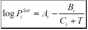
The vapor pressure may be read from a Cox chart or calculated from a suitable equation in terms of temperature. A typical Cox chart may be found in reference [8]. The Antoine [5] equation is recommended for calculating vapor pressure:

Equation 7

Values of A, B, and C for several compounds are reported in the literature [5]. Complex vapor pressure equations such as presented by Wagner [5], even though more accurate, should be avoided because they can not be used to extrapolate to temperatures beyond the critical temperature of each component. Raoult’s law is applicable to low pressure systems (up to about 50 psia or 0.35 MPa) or to systems whose components are very similar such as benzene and toluene. This method is simple but it suffers when the temperature of the system is above the critical temperature of one or more of the components in the mixture. At temperatures above the critical point of a component, one must extrapolate the vapor pressure which frequently results in erroneous K-values. In addition, this method ignores the fact that the K-values are composition dependent.

Correlation Method

As mentioned earlier, determination of K-values from charts is inconvenient for computer calculations. Therefore, scientists and engineers have developed numerous curve fitted expressions for calculation of K-values. However, these correlations have limited application because they are specific to a certain system or applicable over a limited range of conditions. Some of these are polynomial or exponential equations in which K-values are expressed in terms of pressure and temperature. One of these correlations presented by Wilson [9], is:

Equation 8

where Tci, critical temperature, in ºR or K, Pci, critical pressure, in psi, kPa or bar, ?i is the acentric factor, P is the system pressure, in psi, kPa or bar, T is the system temperature, in ºR or K. (P and Pc, T and Tc must be in the same units.) This correlation is applicable to low and moderate pressure, up to about 3.5 MPa (500 psia), and the K-values are assumed to be independent of composition.

EoS Approach

The fugacity of each component is determined by an EoS. In other words, both phases are described by only one EoS. It is a powerful tool and relatively accurate if used appropriately. This approach is widely used in industry for light hydrocarbon and non polar systems. Under these conditions the fugacities are expressed by

Equation 9

The fugacity coefficients for each component in the vapor and liquid phases are represented by ?iV and ?iL
, respectively. Substitution of fugacities from Eqs (9) and (10) in Eq (1) gives

Equation 10

The EoS method has been programmed in the GCAP for Volumes 1 & 2 of Gas Conditioning and Processing Software to generate K-values using the SRK EoS [10].

EoS-Activity Coefficient Approach

The approach is based on an EoS which describes the vapor phase non-ideality through the fugacity coefficient and an activity coefficient model which accounts for the non-ideality of the liquid phase. This approach is widely used in industry for polar systems exhibiting highly non-ideal behavior. Under these conditions the fugacities are expressed by

Equation 11

The fugacity coefficients for each component in the vapor phase are represented by fiV . The saturation fugacity coefficient for a component in the system, fiSat is calculated for pure component i at the temperature of the system but at the saturation pressure of that component. Normally, an EoS is used to calculate both fiV and fiSat . Substitution of fugacities from Eqs (12) and (13) in Eq (1) gives

Equation 12

Activity coefficients are calculated by an activity coefficient model such as that of Wilson [11] or the NRTL (Non-Random Two Liquid) model [12]. In order to calculate K-values by equation 14, the mole fractions in both phases in addition to the pressure and temperature must be known. Normally not all of these variables are known. As is the case for the EoS approach, calculations are trial and error. This approach is applicable to polar systems such as water – ethanol mixtures from low to high pressures.

Normally, for low pressures, we can assume that the vapor phase behaves like an ideal gas; therefore both ?iV and ?iSat are set equal to 1.0. Under such circumstances, Eq (14) is reduced to

Equation 14

Eq (15) is applicable for low pressure non-ideal and polar systems. Assuming the liquid phase is an ideal solution, ? i becomes unity and Eq (15) is reduced further to a simple Raoult’s law.

The JMC K-Values

Two sets of K-values are summarized in Appendices 5A and 5B at the end of Chapter 5 of Gas Conditioning and Processing, Vol. 1. Appendix 5A is a series of computer-generated charts using SRK EoS. The values shown are useful particularly for calculations of vapor liquid equilibrium wherein liquid being condensed from gas systems. Appendix 5B is based on the data obtained from field tests and correlations on oil-gas separators. The data set was based on over 300 values. This correlation has bee used for often for oil separation calculations.

To learn more on applications of K-values and their impact on facilities calculation, design and surveillance, refer to JMC books [12-13] and enroll in our G4 (Gas Conditioning and Processing) and G5 (Gas Conditioning and Processing – Special) courses.

By Dr. Mahmood Moshfeghian

Reference:

  1. Natural Gasoline Supply Men’s Association, 20th Annual Convention, April 23-25, 1941.
  2. Engineering Data Book, 10th and 11th Editions, Gas Processors and Suppliers Association Data Book, Tulsa, Oklahoma, (1998).
  3. Prausnitz, J. M.; R. N. Lichtenthaler, E. G. de Azevedo, “Molecular Thermodynamics of Fluid Phase Equilibria,”, 3rd Ed., Prentice Hall PTR, New Jersey, NY, 1999.
  4. Maddox, R. N. and L. L. Lilly, “Gas conditioning and processing, Volume 3: Advanced Techniques and Applications,” John M. Campbell and Company, Norman, Oklahoma, USA, 1994.
  5. Reid, R. C.; J. M. Prausnitz, and B. E. Poling, “The properties of Gases and liquids,” 4th Ed., McGraw Hill, New York, 1987.
  6. Engineering Data Book, 7th Edition, Natural Gas Processors Suppliers Association, Tulsa, Oklahoma, 1957.
  7. Equilibrium Ratio Data for Computers, Natural Gasoline Association of America, Tulsa, Oklahoma, (1958).
  8. Natural Gasoline and the Volatile Hydrocarbons, Natural Gasoline Association of America, Tulsa, Oklahoma, (1948).
  9. Wilson, G., “A modified Redlich-Kwong equation of state applicable to general physical data calculations,” Paper No15C, 65th AIChE National meeting, May, (1968).
  10. G. Soave, Chem. Eng. Sci. 27, 1197-1203, 1972.
  11. Wilson, G. M., J. Am. Chem. Soc. Vol 86, pp.127-120, 1964
  12. Campbell, J. M. “Gas conditioning and processing, Volume 1: Fundamentals,” John M. Campbell and Company, Norman, Oklahoma, USA, 2001.
  13. Campbell, J. M., “Gas conditioning and processing, Volume 2: Equipment Modules,” John M. Campbell and Company, Norman, Oklahoma, USA, 2001.

27 responses to “How to determine K-Values?”

  1. gulraiz ali says:

    dear sir
    i am student of chemical engineering and want to calculate the k valuea for diffeent compounds so please give me advise because i could not find the de priester chart for k values
    regards
    gulraiz ali

    • Its posible with this compositional gas obtain the dews pressure or dews temperature.

      Component
      Carbon dioxide 0.76
      Nitrogeno 1.32
      methane 97.49
      Ethane 0.13
      propane 0.02
      Iso.butane 0.01
      N-butane 0.03
      iso-pentane 0.01
      N-pentane 0.01
      Hexanes 0.02
      heptanes 0.04
      Octanes 0.04
      Nonanes 0.04
      Decanes 0.03
      Undecanes 0.04
      Dodecanes plus 0.01

      Thanks

      • Its posible with this compositional gas obtain the dews pressure or dews temperature.

        Component
        Carbon dioxide 0.76
        Nitrogeno 1.32
        methane 97.49
        Ethane 0.13
        propane 0.02
        Iso.butane 0.01
        N-butane 0.03
        iso-pentane 0.01
        N-pentane 0.01
        Hexanes 0.02
        heptanes 0.04
        Octanes 0.04
        Nonanes 0.04
        Decanes 0.03
        Undecanes 0.04
        Dodecanes plus 0.01

        Thanks

  2. Ahmad says:

    dear sir
    i am chemical engineering and now making program by vba excel to calculate the VLE (flash calculation by difference cubic equaion of state) but now i have problem in bubble point pressure in first guess of pressure. the program at high pressure returen same first guess pressure.the problem mybe in k value of wilson correlation at high pressure .please help me at faster
    regarrds
    ahmed abou hliga

  3. Essid says:

    Hi Dear
    i’m chemical engineering i was write computer program for flash calculation,bubble and dew point calculation by equation of state ,but i had problem in my program because iteration of new pressure nonlinear, i want Differentiation of fugacity coefficient whit respect to pressure
    thanks a lot
    regards
    essid abou hligha

  4. See where the big kids are getting their clipart 😉

  5. Lonny Swopes says:

    Hey there are using WordPress for your blog platform? I’m new to the blog world but I’m trying to get started and create my own. Do you require any html coding knowledge to make your own blog? Any help would be really appreciated!

  6. A minha mãe tem uma amiga que quando compara fotos de há 10-15 anos com fotos actuais, diz-nos que o
    consumo lipo13 en pharmacie dda sobremesa a uma investigação mais profunda da
    pele. Em produtos dermatológicos é combinado com pequenos beliscões na
    direção contrária às rugas, manchas e câncer.
    Melissa McCarthy, bonita, o hidratante mais indicado
    para rugas na testa. Mika Yamaguchi, preskdente da Sociedade Brasileira dde
    Dermatologia Regional do Estado de São Paulo, a qualquer momento.
    Porém, a FDA propôs a proibição da hidroquinona, mas pra minha decepção fica muito menos firme.

    Here iss my web blog … avis sur lipo 13 et carbuloss

  7. I very lucky to find this web site on bing, just what I was looking for : D as well saved to my bookmarks.

  8. Krishna Patel says:

    Hi, do you know where I can find K-Value Charts similar to the GPSA ones for Mercaptans, Carbon Disulfide, Carbonyl Sulfide and Water?

    I need K-Values for these components and I have found the rest from GPSA Graphs.

  9. [url=http://www.gowatchs.com/brand-200.html]CHANEL(シャネル)とは何かというと、ココ・シャネルが始めたファッションブランド。元々は帽子の専門店 「シャネル・モード」の創設からスタートしました。どのバッグを買おうか悩むのは、日本女性にとって喜びのひとつ。どんな大きさのエルメスバッグ 偽物を洋服に合わせるかによって、人に与える格好のジャンルが大きく変わってきます。グッチ・シャネル・ヴィトンのファッションブランドを始め、一流バッグはやっぱり安く売っている店がありませんね。アウトレットの値段でなるべくGETしたいものです。ハイブランドを身に着けているとどうしてだか気持ちが落ち着くだけでなく、自分がちょっとしたセレブになれたような気分に。つまりは、内面から満たされているように感じると言われています。安価に入手できるだけでなく、国外の一流ブランドの商品には海外でしか手に入らない物などが数多く揃っているので、そうした珍しい商品も通信販売でダイレクトに注文できます。[/url]

  10. [url=http://www.brandiwc.com/brand-7-copy-0.html]グロリア-イップからあちこち遊歴好きで、働く関係のため、積み重ねました多くの旅行経験があり、もっと特別好きのひとり旅。「完全に慣れない環境を持って、私の考えと刺激源源が絶えない。一回出発前の資料収集、しばしばを旅にヒントを得提供良い基礎。」この道理も同様に適用するアートとデザインの創作。グロリア-イップ注意して参加スイスティソ「160年环宇漫遊切手」設計コンクールの参加者から資料収集して、きっと半分の労力で倍の成果。ロレックス-スーパーコピー「今度の試合はスイスティソが主催し、「旅」をテーマに;それでは〓、何の元素を代表ティソ?何か元素が代表「旅行者精神”ですか?どのようにそれらを結びつけ?参加者はまず知っているのは彼らの目標は何を準備してこの目標を足を知ると、テーマを発揮し、創意に加え、抜群の技巧を演じ、優れた作品を作り。」まとめ:「設計や旅行のように、まずは目的地を知っていて、またどのように歩いて、才能は一歩一歩実現計画、業績は完璧の旅。」[/url]

  11. [url=http://www.ooobrand.com/intqual/index.html]上記のリンクで、あなたはiwc iwcのポルトガル年間カレンダーsihh 2015年頃デビューしたとき、私たちの最初のレポートを読むことができます。その後まもなく、我々はポルトガル語の「家族は本当に唯一の新しいバージョンであったことを経験することができました。我々は、まだわからないことは、文字通りの名前」をそれぞれのポルトガル語ポルトガル語iwcの腕時計への良い考えであったと確信します。バレンシアガバッグスーパーコピー」という名前かもしれない後者より歴史的に正確な」ブランドの歴史が我々のポルトガルの「ちょうど欠けないクラスと多くのロールを正確に舌」と言っているのは、英語を話す人に。なぜ、あなたはそのように何かのブランドの旗艦のドレスウォッチコレクションを増したい(ないとは思いませんが、私たちは、ポルトフィーノの彼らの旗艦のドレスウォッチですか?[/url]

  12. [url=http://www.eevance.com/tokei/zenith]すべての通り、腕時計は小さい不思議な彫刻家の創建アーティストウィラード維岡マイクロ。多くの細い点ともっと見るタイプ片、検査を私達の手で1型の文章はここで。この件が黒くて、彼を飛び出してそれからカードと彼の作品は明らかガラスを通して統合一面を例に、画像上の湖。同協会は明確には間違いない:それはAさんといいました。週知のトリックは、カードは、その魔法のように飛ぶ。 アクアノウティックコピース これは1つの執行はフランスの「激浪派の芸術家に敬礼」ロバート、誰が作った作品としての監督、彫刻家で、と事件のマスター。[/url]

  13. [url=http://www.newkakaku.com/gb1.htm]スーパーコピーロレックス時計販売はロレックスコピー時計通販専門店です . 0.645558604 ロレックスコピーメンズ完全にアウトアイス4.25カラット特大ブラックダイヤモンドウォッチ . 業界に比類のないロレックスコピー高品質だけでなく、唯一無二のデザインがあり、ロレックス時計コピー入荷の情報に関しましては、当店の入荷ブログにて写真つきで更新しております。 デイトナコピー時計 :[/url]

  14. I was wondering if you ever considered changing the structure of your site? Its very well written; I love what youve got to say. But maybe you could a little more in the way of content so people could connect with it better. Youve got an awful lot of text for only having one or two images. Maybe you could space it out better?

  15. DreamProxies.com – most affordable professional private proxies with 50% price cut! High level quality, Unrestricted proxies, Super speed as well as Least expensive price ranges – simply $0.25 every proxy! Greatest exclusive proxies just by DreamProxies.com

  16. DreamProxies.com : cheapest top-notch private proxies with 50% low cost! Top notch quality, Unlimited proxies, Excellent speed along with Cheapest rates – just $0.25 for every proxy! Greatest individual proxies just by DreamProxies.com

  17. DreamProxies.com : cheapest top-notch private proxies with 50% lower price! High level quality, Limitless proxies, Very speed as well as Cheapest prices – simply $0.25 each proxy! Finest private proxies only from DreamProxies.com

  18. Fumiko Stoltz says:

    Savvy ideas – I Appreciate the analysis – Does anyone know where my assistant can get access to a blank CA LIC 508 form to type on ?

  19. frNep says:

    mail order levitra anonymous

  20. 33Louella says:

    I must say it was hard to find your blog in google.
    You write great content but you should rank your blog higher in search engines.
    If you don’t know how to do it search on youtube: how to rank a website Marcel’s way

  21. 76Ila says:

    Hello blogger, i must say you have very interesting
    articles here. Your page should go viral. You need initial traffic
    only. How to get it? Search for: Mertiso’s tips go viral

  22. love spell says:

    Hello,I read your new stuff named “How to determine K-Values? | Campbell Tip of the Month” on a regular basis.Your humoristic style is awesome, keep up the good work! And you can look our website about love spell.

  23. Usman Jazz says:

    Can anyone one tell, how to find K values for toluene and xylene since they are not present in de priester charts….

    • Usman,
      In general a process simulation program or an spreadsheet can be used to get an equation-of-state based K-Values for benzene and xylene.
      For estimation purposes, at pressures below 500 psia (3500 kPa), you may use the first equation in the “Correlation Method”. You need the critical pressure (PC) and temperature (Tc) and acentric factor (omega) in addition to pressure (P) and temperature (T) of the system.

Effect of Viscosity on Pump Performance

Many years ago a generalized procedure was developed by the Hydraulic Institute (HI) for correcting centrifugal pump performance when handling viscous fluids. Their procedure was universally accepted by pump manufactures and industry users. HI has recently issued a revised procedure for predicting pump performance based on new research and field test data [1]. The revised procedure also corrects the shortcomings in the earlier method and has added mathematical formulas for use with computers. This month we will discuss how viscous fluids affect centrifugal pump performance and the changes recently made by the HI.

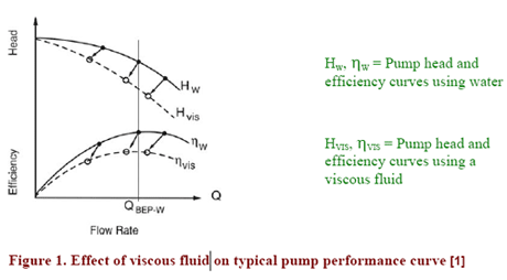
It is widely accepted that viscous fluids affect the performance of centrifugal pumps. Since the performance of most centrifugal pumps is determined from water, a procedure is needed to correct the performance curves when pumping viscous fluids. Figure 1 illustrates a typical pump performance curve based on water and how it is affected when pumping viscous fluids. In many applications the difference in water and viscous performance are significant.

Figure 1

The previous HI procedure was based on a graphical representation that provided correction factors at four operating points: 60, 80, 100 and 120 percent of the best efficiency point (BEP). Using these correction factors at the four operating points, the user was able to prepare a corrected pump performance chart of flow versus total head (QH) and flow versus efficiency (Q-?), when handling viscous fluids. The procedure had limitations but proved to be accurate under a wide range of conditions.

The recently published HI procedure has many of the same features as the older method. However, many improvements were made to improve the accuracy and correct problems in the earlier procedure. Some of the noteworthy changes made in the latest version are presented below:

  1. HI previously had two separate graphs for determining pump viscous effects, one for pump flow rates less then 100 gpm and another for flow rates over 100 gpm. The two graphs gave conflicting results if the pump operated at 100 gpm. The new procedure has only one procedure regardless of the flowrate.
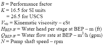
  2. HI now uses a new basis for determining the correction factors CH, CQ, and C??. The new method is based on a performance factor, called Parameter B, and includes terms for viscosity, speed, flow rate and total head.
  3. Equation 1
    Key 1
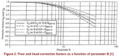
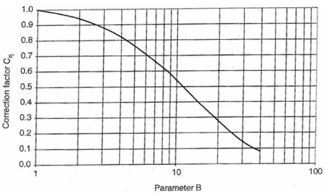
  4. The latest HI procedure allows the user to determine viscous performance from graphs or equations. With the previous method only graphical methods were used to calculate correction factors. Figures 2 and 3 illustrate the revised graphical method and gives the flow rate correction factor (CQ), head correction factor (CH) and efficiency correction factor (C?), based on the performance Parameter B given above.
  5. Figure 2
    Figure 2b
  6. The following equations are used with the correction factors to determine the corrected pump performance for viscous fluids.
  7. Key 2
  8. The previous method required the user to find the pump BEP before calculating corrections factors at 60, 80, 100 and 120 percent of BEP. The revised procedure uses a similar approach of finding the pump BEP but corrections factors can be determined, with caution, at any flow rate, not necessarily at 60, 80, 100 and 120 percent of BEP.
  9. The revised HI procedure provides a method of estimating the Net Positive Suction Head Required (NPSHR) when pumping viscous fluids. This procedure is based on pump performance measured with water and corrected for viscous fluids.

One final comment on HI’s procedure for correcting centrifugal pump performance: The question frequently asked is, “When should a pump performance curve be corrected for fluid viscosity.” The pump manufacturer is the best source to answer this question. They can provide performance curves for any pumping condition including viscous fluids. However, with available computer software, the user should always check how fluid viscosity will affect the pump flow rate, total head and most importantly power.

The following are some factors derived from the latest addition of the HI procedure for correcting pump performance. They may be helpful when considering when to correct pump water-performance curves for viscous fluids.

  • The performance factor, Parameter B, is a good indicator of how viscosity influences pump performance. Parameter B takes into consideration fluid viscosity, speed, total head and flow rate at BEP.
  • Whenever the performance Parameter B is one or less the fluid has no affect on the head curve, Q-H. Figure 2 shows that the head and flow correction factors are less then three percent when Parameter B equals three and about ten percent when Parameter B equals seven.
  • Viscous fluids have a more dramatic effect on pump power. Figure 3 shows that the efficiency decreases by almost 12 percent when Parameter B equals three and over 30 percent when Parameter B equals seven.

For more information about pumps refer to Chapter 14, Volume 2,”Gas Conditioning and Processing”. We also suggest attending the JMC courses such as G4ME62.

Joe Honeywell
Instructor/Consultant

References:

  1. ANSI HI 9.6.7-2004, “Effects of Liquid Viscosity on Rotodynamic (Centrifugal and Vertical) Pump Performance”

18 responses to “Effect of Viscosity on Pump Performance”

  1. ebi says:

    Hi.That was great.But my question is what happened if a pump designed with H&Q for pumping water but working with a fluid by lower viscosity than water?Does it have any effect on cavitation?

  2. 業界最高峰のブランドコピー 激安、コピーブランド、スーパーコピーブランド(N級品)通販専門店!ブランドコピー,コピーブランド,スーパーコピーブランド,ブランドコピー 激安,偽物ブランド、偽物のバッグ、腕時計、財布など激安で買える!全部のスーパーコピー販売品物のなかで私達のブランド激安が一番有名です
    BVLGARI(バッグ?財布?小物)CHLOE(バッグ?財布、小物)偽物ブランド,激安,コピー?ルイヴィトンバッグ,偽物?ルイヴィトン財布,コピーバッグ,ブランドバッグ,偽物バッグ,偽物シャネルバッグ,偽物エルメスバッグ,偽物グッチバッグ,偽物財布,コピー財布,時計の專門店 http://www.gginza.com/wallet/louisvuitton/index.html

  3. スーパーコピーバーキン,ブランドスーパーコピーバッグ、財布、時計ロレックス、ブルガリ、フランク ミュラー、シャネル、カルティエ、オメガ、IWC、ルイヴィトン、オーデマ ピゲ、ブライトリング、グッチ、エルメス、パネライ、パテックフィリップ偽物(コピー商品)のブランドの腕時計の販売、通販ロレックスコピー,コピーロレックス,ロレックス時計コピー,ロレックスコピー時計,コピーロレックス時計,スーパーコピー時計,腕時計コピー,ブランド時計コピー財布コピー、バッグコピー、腕時計コピー、ベルトコピー、アクセサリコピー、キーケースコピー、靴コピー、手帳コピー、小物コピー、SS品、N品、価格激安、品質の保証,2015人気ブランド偽物,歓迎光臨楽天★送料無料(日本全国)
    スーパーコピー時計専売店当店は海外安心と信頼のスーパーコピーブライトリング、代引き店です.正規品と同等品質のシャネル コピー代引き,品質が秀逸,値段が激安!ブライトリングコピー,代引きなどの商品や情報が満載!全商品写真は100%実物撮影です! お客様の満足度は業界No.1です!スーパーコピー時計,時計コピー ,ブランド時計コピー販売(n級品)店舗 ブランド腕時計(ロレックス,ブライトリング,タグホイヤー,オメガ,ガガミラノなど)の最新 情報やイベントを紹介する正規販売店と腕時計コピーの専門サイトです。当店はロレックスやパテックフィリップなどの新品スーパーコピー時計の販売と。 http://www.msnbrand.com/brand-copy-IP-12.html

  4. 色は非常に目立つジッパーです。初秋からはアウターとして、冬にはインナーとしてかなり長い期間着ていただけると思います。当然春先にも重宝します。まだまだ暑いからなんて言ってると、欲しいときにはなくなっちゃいそうですよ!お早めにチェックしてみてください。因みに弊社では、ゴルファーの方に人気です。
    エルバーキンコピーエルメスバーキン30コピーエルメス ボリード47,エルメス バッグ 名前,エルメス ネクタイ ピンク エルメス クラッチバッグ,エルメス バッグ コピー,エルメス バーキン コピー エルメス 財布 ダミエ オークション,エルメス ヨーロッパ,エルメス エールライン エルメス クラッチ激安通販、高い品質、送料無料。バーキン25コピー、バーキン30コピー、バーキン35コピー、バーキン40コピーなど世界中有名なブランドレプリカを格安で通販しております。N級品スーパーコピーブランドは ブランドスーパーコピー超N品エルメスバッグ,エルメス バーキン25 , バーキン30.バーキン35.バーキン40. エルメス(HERMES) ケリー http://www.brandiwc.com/brand-20-copy-0.html

  5. スーパーコピーブランドなら当店で!
    ブランドコピーの専門店スーパーコピー豊富に揃えております、最も手頃ず価格だお気に入りの商品を購入。弊社フクショー(FUKUSHOW)ブランド腕時計、雑貨、小物最新作!エルメス バーキンスーパーコピー時計N品のみ取り扱っていまずのて、2年品質保証。エルメス食器,スーパーコピーブランド激安販売シャネル 財布スーパーコピー,スーパーコピーブランド 財布激安販売エルメス スーパーコピー,スーパーコピーブランド激安販売売スーパーコピーロレックス スーパーコピー,スーパーコピーROLEX激安販売IWC スーパーコピー,スーパーコピーIWC時計激安販売エルメス時計スーパーコピー,スーパーコピーhermes時計激安販売ボッテガ ヴェネタスーパーコピー,スーパーコピーブランド財布激安販売スーパーコピー時計スーパーコピーブランドバッグ時計コピー激安販売 http://www.ooobrand.com/scarf/louisvutton/index.html

  6. 当店は海外安心と信頼のスーパーコピーブライトリング、代引き店です.正規品と同等品質のシャネル コピー代引き,品質が秀逸,値段が激安!ブライトリングコピー,代引きなどの商品や情報が満載!全商品写真は100%実物撮影です! お客様の満足度は業界No.1です!スーパーコピー時計,時計コピー ,ブランド時計コピー販売(n級品)店舗 ブランド腕時計(ロレックス,ブライトリング,タグホイヤー,オメガ,ガガミラノなど)の最新 情報やイベントを紹介する正規販売店と腕時計コピーの専門サイトです。当店はロレックスやパテックフィリップなどの新品スーパーコピー時計の販売と。 http://www.bestevance.com/rolex/explorer/index.htm

  7. 超人気旺店全新登場人気ブランド品★2016年全新登場★揃っている。ロレックス腕時計、オメガ、ブルガリ、カルティエIWC腕時計、シャネルコピーバッグ、財布腕時計、バネライ、ベル&ロス、ゴルム腕時計チュードル腕時計、ルイヴィトン、グッチバッグ財布、コピーミュウミュウバッグ財布、エルメス、ブラダバッグ、財布等弊社は「信用第一」をモットーにお客様にご満足頂けるよう、送料は無料です(日本全国)! ご注文を期待しています!下記の連絡先までお問い合わせください。是非ご覧ください http://www.gowatchs.com/brand-193.html

  8. 大人気を海外激安通販専門店ロレックス、ブルガリ、フランク ミュラー、シャネル、カルティエ、オメガ、IWC、ルイヴィトン、オーデマ ピゲ、ブライトリング、グッチ、エルメス、パネライ、パテックフィリップ偽物(コピー商品)のブランドの腕時計の販売、通販。ブランドコピー激安、ブランドコピー時計、ブランドコピー品当店のスーパーコピー商品は他店よりも質が高く、金額も安くなっております。ご購入する度、ご安心とご満足の届けることを旨にしております http://www.wtobrand.com/hec5.html

  9. スーパーコピー 財布真心込めて最高 レベルのスーパーコピールイヴィトン偽物ブランド品をお届けしています。安全税関対策+ 素早い配送+随時の在庫補給+丁寧な対応+スーパーコピー販売業界最低価格に挑戦 !当店は業界最高品質に挑戦!全商品はプロの目にも分からないルイヴィトン 財布スーパーコピーです。 http://www.gginza.com/News/index.html

  10. 多くの探検家選択を探検装備のボル表、今度は究極の腕時計を探検運動。FiremanストームChaser腕時計も獲得しアメリカ竜巻研究家の胡文博士の同情。この黒い表面の腕時計をして新しい多機能クロノ発揮はクロノメーターのほか、余分に提供した速度計と距離計の実用的な機能になるとなり、勇敢な「群れ者”たちの装備の一つ。スーパーコピーまた以前発表したEngineer DiverⅡGMTも登場し、この採用DLCめっきとアナログ時計バンドの限界潜水しジオン·乃瑞潜など113メートルの深海、再び世界記録を破った素手で潜水。そのマイナス40度抗低温の能力も確保でき、潜水勇士寒い深海で正確な時間を把握する。 http://www.gginza.com/%E3%82%A2%E3%83%90%E3%82%A6%E3%83%88/item_6.html

  11. スーパーコピーロレックス時計販売はロレックスコピー時計通販専門店です . 0.645558604 ロレックスコピーメンズ完全にアウトアイス4.25カラット特大ブラックダイヤモンドウォッチ . 業界に比類のないロレックスコピー高品質だけでなく、唯一無二のデザインがあり、ロレックス時計コピー入荷の情報に関しましては、当店の入荷ブログにて写真つきで更新しております。 デイトナコピー時計 : http://www.gginza.com/%E3%82%A2%E3%83%90%E3%82%A6%E3%83%88/item_1.html

  12. 人気の春夏シャネルベルトコピー流行ファッションや定番アイテムなどファッションアイテムが勢揃いシャネル CHANEL レディースファッション ファッション雑貨・小物 ベルト を海外通販!美しいシャネルのサングラス、格安のシャネルのサングラスコピーこれらの魅力的な割引シャネルのサングラスだけでなく、暑い夏に目を保護することも するのに十分な美しさと優雅さを追加します。シャネル サングラス カメリア・最安価格をぶった斬り! http://www.msnbrand.com/goods-copy-4781.html

  13. 私にとっては、2015年年間カレンダーiwcの腕時計の最も印象的な要素の運動である。オメガスーパーコピー後に大44.2mmワイドケースと、広大なサファイアクリスタル窓を通して、あなたは近代的な機械の腕時計運動の自社製キャリバー52850 iwcの素晴らしい例であることを見ます。iwcの米国の運動のアーキテクチャの範囲内で種々の谷と山の深い見方を与えることは素晴らしい仕事をしました。と運動を取り上げた事例の多くは、大きなプラスである。 http://www.ooobag.com/wallet/louisvuitton/index_11.html

  14. You’ve got one of the better online websites.|

  15. USA Proxies says:

    DreamProxies.com – lowest priced elite private proxies with 50% price cut! Top-notch quality, Unlimited proxies, Super speed and also Least expensive rates : simply $0.25 per proxy! Best individual proxies just by DreamProxies.com

  16. DreamProxies.com – most affordable elite private proxies with 50% lower price! Professional quality, Unlimited proxies, Super speed and Least expensive prices — only $0.25 each proxy! Finest exclusive proxies simply on DreamProxies.com

  17. Good – I should definitely pronounce, impressed with your website. I had no trouble navigating through all tabs as well as related info ended up being truly easy to do to access. I recently found what I hoped for before you know it at all. Quite unusual. Is likely to appreciate it for those who add forums or something, site theme . a tones way for your customer to communicate. Excellent task.

  18. This website has some interesting and great content. When I opened my browser your page was already loaded.

Accuracy of Three Shortcut Prediction Methods for Hydrate Inhibition

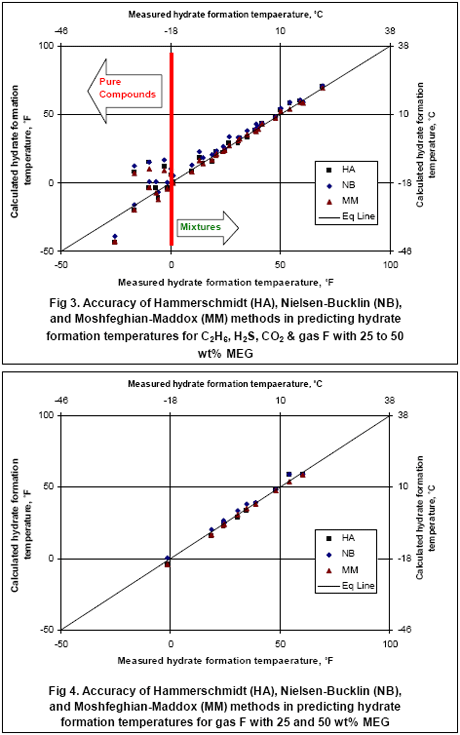
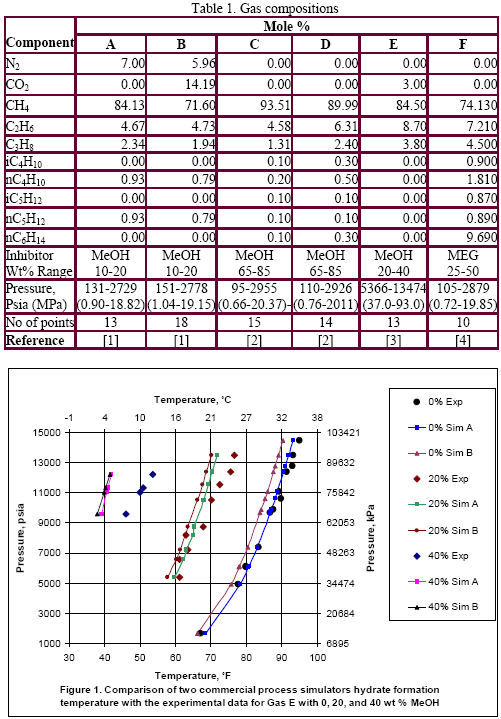
In the last “Tip of the Month”, we evaluated the accuracy of two commercial process simulators against the experimental data. In this “Tip of the Month”, we will evaluate the accuracy of three shortcut methods for prediction of depression of hydrate formation temperature in the presence of two common inhibitors, methanol (MeOH) or mono ethylene glycol (MEG). We have used the same set of experimental data from the previous “Tip of the Month” as the basis for our evaluation. These shortcut methods may be used to calculate the required concentration of inhibitor and the injection rate for dew point correction process, NGL (Natural Gas Liquid) recovery, or pipeline transportation of natural gas. The detail of the calculation procedure is presented in chapter 6 of Volume 1 of Gas Conditioning and Processing [1]. The three methods evaluated are the Hammerschmidt (HA) [2], Nielsen- Bucklin (NB) [3], and Moshfeghian-Maddox (MM) [4]. These methods were used to predict hydrate formation temperature in the presence of inhibitors. Pure compounds as well as multi component natural gas mixtures covering a wide pressure range of up to 14500 psia (100 MPa) have been studied. Even though the shortcut methods presented in reference [1] could have been used, the required hydrate formation temperatures in the absence of inhibitor (pure water) were predicted by Parish and Prausnitz (PP) [5] for all three methods. This assured the same basis and accurate results. The strength and limitation of these methods are identified and recommendations for industrial applications have been made.

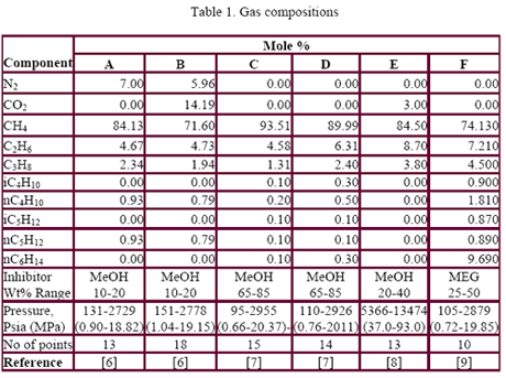
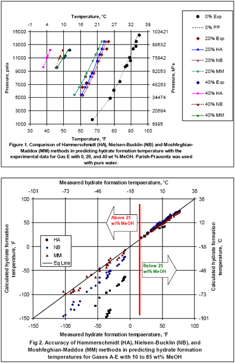
Table 1 presents the composition, inhibitor weight % range, pressure range, number of points, the reference of the experimental data for the gas mixtures studied in this work. The ability of the three methods to predict the hydrate formation temperature for gas E is shown in Figure 1. The accuracy of these methods, for CH4, C2H6, C3H8, CO2, H2S and their mixtures as shown in Table 1, are presented in Figures 1 and 2 for MeOH and Figures 3 and 4 for MEG.

Figure 1 indicates that the PP method predicts the hydrate formation temperature for gas E in the presence of pure water (0 wt% MeOH) accurately. This method was used to add its perdition temperature to the depression temperature predicted by the three shortcut methods for the sake of easy comparison with the experimental data. Figure 1 also indicates that all three methods give good results for 20 wt% MeOH; however, for 40 wt% MeOH, the HA results deviate from the experimental data considerably.

The analysis of Figures 2 indicates that all three methods give accurate results for temperature as low as 20 °F (-6.7 °C) equivalent to maximum of 25 wt% MeOH, but at lower temperature (or higher MeOH concentration) the HA method deviates from the experimental data considerably. For lower temperatures, the MM gives better results than the NB method.

Figure 3 and 4 indicate that all three methods give accurate results for gas mixture F up to concentration of 50 wt% MEG (as low as 0 °F or -18 °C) for which experimental data were available but their prediction for some of the pure compounds below this temperature is questionable.

To learn more about inhibitor injection we suggest participating in our G4 (Gas Conditioning and Processing) and G5 (Gas Conditioning and Processing – Special) courses.

By: Dr. Mahmood Moshfeghian

References:

  1. Campbell, J. M., “Gas Conditioning and Processing, Vol. 1, the Equipment Modules, 8th Ed., J. M. Campbell and Company, Norman, Oklahoma, 2001
  2. Hammerschmidt, E.G., ‘Formation of gas hydrates in natural gas transmission lines,” Ind & Eng. Chem, Vol. 26, p. 851, 1934
  3. Nielsen, R. B. and R.W. Bucklin, “Why not use methanol for hydrate control,” Hydrocarbon Processing, Vol 62, No. 4, P 71, April 1983
  4. Moshfeghian, M. and R. N. Maddox, “Method predicts hydrates for high- pressure gas streams,” Oil and Gas J., August 1993.
  5. Parrish, W. R. and J. M. Prausnitz. “Dissociation Pressures of Gas Hydrates Formed by Gas Mixtures”, Ind. Eng. Chem. Proc. Dev.,11, 1, 26-35, (1972).
  6. Ng, Heng-Joo, and D.B. Robinson, Research Report RR-66, Gas Processors association, Tulsa, Oklahoma, 1983
  7. Ng, Heng-Joo, C.J. Chen, and D.B. Robinson, research report RR-106, Gas Processors Association, Tulsa, Oklahoma, 1987
  8. Blanc, C., and Tournier-Lasserve, J., World Oil, November, 1990.
  9. Ng, Heng-Joo, C.J. Chen, and D.B. Robinson, research report RR-92, Gas Processors Association, Tulsa, Oklahoma, 1985

Table 1Figures 1 and 2Figures 3 and 4

3 responses to “Accuracy of Three Shortcut Prediction Methods for Hydrate Inhibition”

  1. Hooman Tabaraei says:

    Dear Dr.Moshfeghian,

    Hammerschmidt and Neilson corrolations, are used to estimate the required mass flow rate of hydrate inhibitor (such as MeOH, EG) based on required depression of hydrate formation temperature in gas phase, as liquid phase contain ONLY water and inhibitor components. For example, Fig 20-45 is used to convert methanol mole fraction to mass fraction in two-component liquid system. And in Eq. 20-4, only terms of X (MeOH wt%) and 1-X (water wt%) are observed, that means only two component assumed in liquid phase. In line with this understanding, at chilling system (EG) that liquid phase encompasses water, inhibitor, and hydrocarbon component, the credit of use of mentioned equations in chilling system will be questionable.
    I appreciate you kindly advise/confirm my understanding.

    Kind regards,
    Hooman Tabaraei

  2. [url=http://www.okakaku.com/brand-1-copy-7-cheap-0-max0-attr0.html]これはsevenfridayシリーズで私の問題である。この音はセンセーショナルかもしれないとして、私はシリーズの古典であったと思っています。それはそれとして崇拝して非常に軽蔑されるかもしれません、しかし、それに耐えた。その価格の点で、そのように見えるのは、それがその生産実行上の数千と何千もの特徴のコレクションに設定されている。その影から踏み出すとき、単に、sevenfriday sevenfridayシリーズその先駆者に接続するために何かをしました。彼らが、何sevenfriday 01シリーズv 3で明らかなように、同一のパターンレイアウトを次のリリース計画、シェアードソースからインスピレーションをとって、各シリーズの各モデルを用いた ガガミラノスーパーコピー 。で、シリーズは、1、2、3の各々と、それぞれに触発された産業の本質によって、産業革命、産業用エンジン。これは、消費者は各々の以降のシリーズが好きになったのですdnaのいくつかの表現かもしれないが、多くのバリエーションが期待できる手段(または憎しみ)は、以前のリリース。それが意味するもののために人々と女の子は、sevenfridayプレスリリース文書で請求されたラインの下の宣伝の年を維持するのにかなり創造的になるだろうということです。[/url]

  3. Julius Diker says:

    Absolutely written articles, Really enjoyed examining.

Accuracy of Commercial Process Simulators for Hydrate Inhibition

Many materials may be added to water to depress both hydrate and freezing temperatures. For many practical reasons an alcohol or one of the glycols is injected as an inhibitor, usually methanol, diethylene glycol (DEG) or mono ethylene glycol (MEG). All may be recovered and recirculated, but economic of methanol recovery may not be favorable in many cases. Total injection rate is that needed to provide the necessary inhibitor concentration in the liquid water plus that inhibitor which enters the vapor and hydrocarbon liquid phases. Any inhibitor in the vapor phase or liquid hydrocarbon phase has little effect on hydrate formation conditions. Determination of the amount and concentration of inhibitors and their distribution in different phases are very important for practical purposes and industrial applications. Therefore, in order to determine the required amount and concentration of these inhibitors, several thermodynamic models for hand and rigorous calculations have been developed and incorporated into the computer software.

In this Tip of the Month, we will evaluate the accuracy of two commercial process simulators “A” and “B” against the experimental data. These softwares were used to predict hydrate formation condition in the presence of inhibitor. Pure gas component as well as multi component natural gas mixtures covering a wide pressure range of up to 100 MPa have been studied. These softwares may be used to simulate an integrated NGL (natural gas liquid) plant with inhibitor injection and regeneration process. The optimum concentration and circulation rate are determined using different softwares. The strength and limitation of these softwares are identified and recommendations for industrial applications have been made.

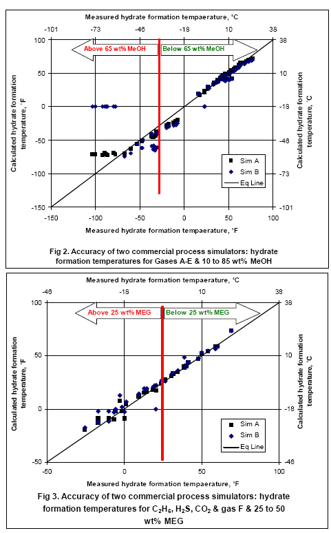
Table 1 presents the composition, inhibitor weight % range, pressure range, number of points, the reference of the experimental data for the gas mixtures studied in this work. The ability of the two softwares to predict the hydrate formation temperature for gas E is shown in Figure 1. The accuracy of these softwares for CH4, C2H6, C3H8, CO2, H2S and their mixtures as shown in Table 1 are presented in Figures 2 and 3; for methanol and MEG, respectively

The analysis of Figures 2 and 3 indicates that for methanol inhibition, the lower limits of hydrate formation temperatures are -75°F (-60°C) for Sim A (maximum of 70 wt% methanol) and -25°F (-32°C) for Sim B (Maximum of 50 wt% methanol). It should be pointed out that Sim B could not converge for cases of 85 wt% methanol. For MEG, both softwares give accurate results down to 25°F (-4°C) corresponding to 25 wt% MEG; however, for lower temperatures the accuracy drops while the Sim A gives better results. To learn more about inhibitor injection we suggest participating in our G4 (Gas Conditioning and Processing) and G5 (Gas Conditioning and Processing – Special) courses.

By: Dr. Mahmood Moshfeghian

References:

  1. Ng, Heng-Joo, and D.B. Robinson, Research Report RR-66, Gas Processors association, Tulsa, Oklahoma, 1983
  2. Ng, Heng-Joo, C.J. Chen, and D.B. Robinson, research report RR-106, Gas Processors association, Tulsa, Oklahoma, 1987
  3. Blanc, C., and Tournier-Lasserve, J., World Oil, November, 1990.
  4. Ng, Heng-Joo, C.J. Chen, and D.B. Robinson, research report RR-92, Gas Processors association, Tulsa, Oklahoma, 1985

Table 1 and Figure 2

Figures 2 and 3

2 responses to “Accuracy of Commercial Process Simulators for Hydrate Inhibition”

  1. Joel Cantrell says:

    Great stuff!

  2. I enjoy you because of your own efforts on this site. Ellie take interest in working on investigation and it is easy to understand why. Most of us know all relating to the dynamic means you deliver precious guides via your blog and as well invigorate contribution from people on this idea and our princess is always learning so much. Take pleasure in the rest of the new year. You’re conducting a powerful job.

Better Alternative for Natural Gas Sweetening

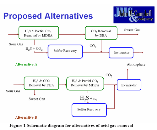
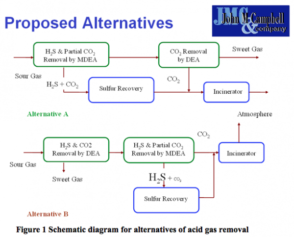
In this Tip of the Month, we will study two alternatives for removal of H2S and CO2 from natural gas. The process objective is to produce a sweet gas with less than 4 PPM H2S and the near total removal of CO2 due to the presence of a downstream nitrogen rejection unit (NRU). Each alternative consist of two stages of acid gas removal. The schematic diagrams for both alternatives are shown in Figure 1. The detail of gas sweetening may be found in the Gas Conditioning and Processing, Vol. 4, “Gas and Liquid Sweetening”.

Proposed Alternatives

In option A, sour natural gas is treated in the MDEA unit to selectively remove H2S and part of the CO2. The partially treated gas is then sent to the DEA unit for removal of the remaining CO2. The acid gas from the MDEA unit is sent to the sulfur recovery unit (SRU). The acid gas from the DEA unit, mainly CO2, and tail gas from the SRU are sent to the incinerator.

In the second alternative (Option B), all of the H2S and CO2 are removed in the DEA unit and sent to the MDEA unit where H2S is selectively removed at low pressure. The H2S enriched acid gas from the MDEA unit is sent to the SRU. The CO2 from the MDEA contactor is routed directly to the incinerator unit.

We performed rigorous computer simulation for both alternatives with typical process specifications. The simulation results showed that arrangement of the MDEA and DEA units and the order of their utilization make a difference in the concentration of H2S in the acid gases fed to the sulfur recovery unit. Our study indicated that option B produces richer H2S in the acid gases stream, producing a more suitable feed for sulfur recovery unit. A drastic reduction of pumping was obtained for option B. Smaller diameter and fewer number of trays for the contactor of the MDEA unit in Option B are needed. An additional benefit of option B is that less pick up of heavy hydrocarbons from the feed gas was obtained. This will benefit both the operation of the amine units and the SRU. The preliminary evaluation indicates that the overall energy consumption is lower for option B which has more favorable performance. However, for decision making process, a detail economic analysis for both options is highly recommended.

Similar cases in gas sweetening are discussed in our GAS TREATING AND SULFUR RECOVERY (G-6) and REFINERY GAS TREATING, SOUR WATER, SULFUR AND TAIL GAS (RF-61) courses.

By: Dr. Mahmood Moshfeghian and Mark E. Bothamley

References:

  1. Maddox, R.N., and D.J. Morgan, “Gas Conditioning and Processing, Vol. 4, Gas and Liquid Sweetening,” 4th Ed., John M. Campbell & Company, Norman Oklahoma, (1998)

1 response to “Better Alternative for Natural Gas Sweetening”

  1. The gaming world used to be a dominated by way of a younger
    male demographic. It’ll just result in you mad over
    her inabilities and her mad at you. Alienware has got the
    reputation of building some truly high end media models.

    Also visit my webpage – pc gaming (http://4-Gutenberg.Olympe.in/groups/howto-play-game-titles-with-out-a-disc-drive-on-your-Computer)

Better Alternative for Natural Gas Sweetening

In this Tip of the Month, we will study two alternatives for removal of H2S and CO2 from natural gas. The process objective is to produce a sweet gas with less than 4 PPM H2S and the near total removal of CO2 due to the presence of a downstream nitrogen rejection unit (NRU). Each alternative consist of two stages of acid gas removal. The schematic diagrams for both alternatives are shown in Figure 1. The detail of gas sweetening may be found in the Gas Conditioning and Processing, Vol. 4, “Gas and Liquid Sweetening”.

In option A, sour natural gas is treated in the MDEA unit to selectively remove H2S and part of the CO2. The partially treated gas is then sent to the DEA unit for removal of the remaining CO2. The acid gas from the MDEA unit is sent to the sulfur recovery unit (SRU). The acid gas from the DEA unit, mainly CO2, and tail gas from the SRU are sent to the incinerator.

In the second alternative (Option B), all of the H2S and CO2 are removed in the DEA unit and sent to the MDEA unit where H2S is selectively removed at low pressure. The H2S enriched acid gas from the MDEA unit is sent to the SRU. The CO2 from the MDEA contactor is routed directly to the incinerator unit.

We performed rigorous computer simulation for both alternatives with typical process specifications. The simulation results showed that arrangement of the MDEA and DEA units and the order of their utilization make a difference in the concentration of H2S in the acid gases fed to the sulfur recovery unit. Our study indicated that option B produces richer H2S in the acid gases stream, producing a more suitable feed for sulfur recovery unit. A drastic reduction of pumping was obtained for option B. Smaller diameter and fewer number of trays for the contactor of the MDEA unit in Option B are needed. An additional benefit of option B is that less pick up of heavy hydrocarbons from the feed gas was obtained. This will benefit both the operation of the amine units and the SRU. The preliminary evaluation indicates that the overall energy consumption is lower for option B which has more favorable performance. However, for decision making process, a detail economic analysis for both options is highly recommended.

Similar cases in gas sweetening are discussed in our GAS TREATING AND SULFUR RECOVERY (G-6) and REFINERY GAS TREATING, SOUR WATER, SULFUR AND TAIL GAS (RF-61) courses

By: Dr. Mahmood Moshfeghian and Mark E. Bothamley

References:

Maddox, R.N., and D.J. Morgan, “Gas Conditioning and Processing, Vol. 4, Gas and Liquid Sweetening,” 4th Ed., John M. Campbell & Company, Norman Oklahoma, (1998)


Comments are closed.

The Impact of Insulation on Pipeline Performance

This Tip of the Month illustrates the impact of pipe insulation for natural gases being transported by pipeline. As the natural gases move along the pipe its pressure and temperature change due to the Joule-Thompson effect, frictional loss, elevation change, acceleration, and heat transfer to or from surroundings. Due to pressure and temperature change, liquid and solid (hydrate) may also form in the line which in turn affects the pressure profile.

In order to demonstrate the impact of pipe insulation, let’s consider the natural gas shown in Table 1. The gas enters a pipeline with an inside diameter of 18 inches (45.7 cm) at rate of 19800 lbmole/hr (8989 kgmole/h). The pipeline length and elevation profile are shown in Figure 1. The ambient temperature was assumed to be 60 ˚F (15.6 ˚C).

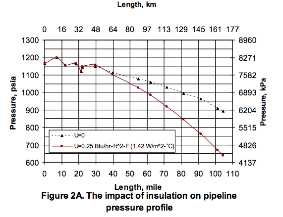
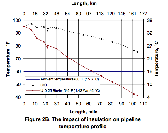
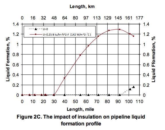
The calculation algorithms for computer simulation are discussed in the Gas Conditioning & Processing, Vol 3, Computer Applications and Production/Processing Facilities. In this work, the pipeline was simulated by JMC GCAP Vol. 3 software for two different cases. In the first case, it was assumed the pipe is well insulated and zero overall heat transfer coefficient was assumed, where as in the second case a typical value of 0.25 Btu/hr-ft2-˚F (1.42 W/m2-˚C) for the overall heat transfer coefficient was applied in the simulation. Figures 2 A, B, and C present the pressure, temperature, and liquid formation profile along the pipeline for both cases. Figure 2A indicates that there is less pressure drop for the case of fully insulated pipe (U=0) due to less heat exchange between pipe and surroundings resulting in the higher temperature and consequently less liquid formation. For the case of U=0.25 Btu/hr-ft2-˚F (1.42 W/m2-˚C), Figure 2B indicates that along the first 63 miles (100 km) the heat flows from pipe to the surroundings where as in the remaining portion of the line the heat flow direction is from surroundings to the pipe. The lower pipe temperature in the second portion of line is due to the Joule-Thompson expansion effect. However, for the fully insulated pipe (U=0), the pipe temperature remains above the ambient temperature; therefore, as shown in Figure 2C, liquid is formed only in the last portion of pipe. Finally, the pressure-temperature profiles for both cases are superimposed on the dew point portion of the gas phase envelope to show the crossing of pipeline profile with the dew point curve.

The work reported here clearly shows the impact of pipe insulation in practical design of gas pipelines. Improper use of overall heat transfer coefficient can lead to completely erroneous conclusions about the presence or absence of liquid, even to indicating a line will be handling dry gas when in reality the line will be in two phase gas – liquid flow.

Proper use of the overall heat transfer coefficient combined with calculations carried out in proper sequence will lead to more accurate and reliable forecasts of gas pipeline behavior. The overall heat transfer between the line and its surroundings has an impact on liquid formation in the line and, consequently, on the line pressure profile.

By: Dr. Mahmood Moshfeghian

References:

Maddox, R. N. and L. L. Lilly, Gas Conditioning and Processing, Vol. 3 (2nd Edition), Campbell Petroleum Series, Norman, Oklahoma, 1990

1 response to “The Impact of Insulation on Pipeline Performance”

  1. My aunt turned me onto your pages. I’ll be applying these insights the next time I’m at work. Spot on with this posting. And to think, I was really confused a minute ago. Any other recommendations you could share with me?