How good is Flanigan Correlation for Two Phase Gas-Liquid Pipeline Calculations?

There are a few computer tools designed specifically for modeling and analysis of complex multiphase systems such as PipePhase, PipeSim, OLGA, and etc [1]. Modeling and simulation of multiphase system, even under steady-state condition, is complex. In the June Tip of the Month (TOTM), we illustrated how the process simulation programs can be used to simulate a natural gas transmission pipeline. These programs are based on mechanistic models and laboratory developed correlations and rely on complex iterative algorithms to perform the tedious calculations.

However, for hand calculation, the Flanigan correlation (which is based on field data for gas dominated transmission pipelines) has been developed and can be used in relatively straight manual calculations. This correlation has proven useful even though it is relatively simple. The relationship between gas flow rate, diameter and pressure drop is represented by Panhandle A gas flow equation (which is based on the Basic Gas Flow Equation modified with field data). The basic equation is single phase flow for gas as is the Panhandle A Equation. The basic equation is derived from basic principles, while the Panhandle A and Flanagan Equation are best fits to a range of field data. Two corrections are made in the Flanagan Equation for two-phase flow:

  1. The value of outlet pressure is adjusted for the pressure loss due to uphill and downhill flow of two phases, including the effect of liquid holdup.
  2. The efficiency term is correlated to reflect measured system performance based on gas velocity and liquid-gas ratio.

For the detail of the Panhandle A equation and the Flanigan correlation, refer to chapter 10 of Gas Conditioning & Processing, Vol 1 [2]. The algorithms for computer simulation are discussed in the Gas Conditioning & Processing, Vol 3, [3].

In this TOTM (which is a continuation of the June TOTM), we will demonstrate the accuracy and application of the Flanigan correlation.

Let’s consider the same case study as was used in the June TOTM. The composition and conditions of the natural gas are shown in Table 1. The gas enters a 20 inch diameter pipeline with an inside diameter of 18.81 inches (47.8 cm) at rate of 180 MMSCFD, equivalent to 19800 lbmole/hr (8989 kgmole/h). The pipeline length and elevation profile are shown in Figure 1. The ambient temperature was assumed to be 60 °F (15.6 °C). The gas enters the line at 1165 psia (8032 kPa) and 95 °F (35 °C). The pipeline is buried under ground with an overall heat transfer coefficient of 1 Btu/hr-ft2-°F (5.68 W/m2-°C). Due to the high content of H2S and CO2 (25.6 and 9.9 mole %, respectively) and to prevent corrosion and hydrate formation, the gas has been dehydrated before entering the pipeline.

Three methods used in this analysis include the basic gas flow equation [2], the Flanigan correlation, and the computer models using the Beggs-Brill correlation with the original liquid hold-up correlation. The SRK equation of state (EOS) was used to perform the phase behavior calculations in the computer based analyses.

The pipeline is divided into 14 segments to match with the number of up-hill and down-hill sections in the line. In addition, each segment is divided into 10 equal increments to achieve higher calculation accuracy. This division is not required for the Flanigan correlation and is done for the sake of comparison with other methods.

Figures 2 through 5 present the pressure, temperature, and liquid formation profiles along the pipeline. Figure 2 indicates that the pressure profiles predicted by the Flanigan matches very well with the results obtained by the more rigorous computer analyses using Beggs-Brill method. However, as expected, due to presence of liquid formation in the line, the basic gas equation results deviate from the two phase flow correlations.

Table 1
Figure 1

Figure 3 indicates that the temperature profiles predicted by the three correlations fall on top of each other. The small amount of liquid condensation in the line has smaller effect on the temperature profile than on the pressure profile. The liquid formation profiles predicted by the three correlations are shown in Figure 4. As shown in this figure, the amounts of liquid formation predicted by the Flanigan and Beggs-Brill correlations match very well, but the liquid formation predicted by the basic gas equation is different from the two-phase correlations. This can be explained by the fact the pressure drop and consequently the temperature change predicted by the basic equation are different from those predicted by the other two methods.

In this study, the same normal boiling point, relative density, and molecular weight for C6+, as shown in Table 1, are used for all three correlations. Therefore, the same predicted critical properties and acentric factor are used. These properties and the binary interaction parameters are needed to perform the phase behavior calculations by a cubic EOS such as SRK. In addition, the same binary interaction parameters between different components and C6+ are used.

Figure 2

The work reported here clearly shows the value of simple Flanigan correlation and how it can used to model and analyze the behavior of a gas transmission pipeline. However, care must be taken to utilize this correlation properly. Even though the Flanigan correlation is simple, its results match very well with the more rigorous method of Beggs-Brill. However, we expect the agreement between these two correlations deteriorate as the amount of liquid formation in the line increases. As expected the basic gas equation predicted smaller pressure drop in the line due to the fact the liquid formation in the line is ignored. Although the Flanagan Equation results are not sensitive to the elevation correction term, it is important to include the elevation term with a reasonable estimate of the total upward and downward elevation changes. The results are also relatively insensitive to the efficiency factor, therefore average values for liquid and gas ratios can be used for each segment.

Similar cases of fluid flow are discussed in our Fundamentals of Onshore and Offshore Pipeline Systems – PL-4; Onshore Pipeline Facilities – Design, Construction and Operations – PL-42Flow Assurance for Pipeline Systems – PL-61courses.

By: Dr. Mahmood Moshfeghian

References:

  1. Ellul, I. R., Saether, G. and Shippen, M. E., “The Modeling of Multiphase Systems under Steady-State and Transient Conditions – A Tutorial,” The Proceeding of Pipeline Simulation Interest Group, Paper PSIG 0403, Palm Spring, California, 2004.
  2. Campbell, J. M., and Hubbard, R. A., Gas Conditioning and Processing, Vol. 1 (8th Edition, 2nd Printing), Campbell Petroleum Series, Norman, Oklahoma, 2001.
  3. Maddox, R. N. and L. L. Lilly, Gas Conditioning and Processing, Vol. 3 (2nd Edition), Campbell Petroleum Series, Norman, Oklahoma, 1990.

Figure 3Figure 4Figure 5

1 response to “How good is Flanigan Correlation for Two Phase Gas-Liquid Pipeline Calculations?”

  1. The new style of cheap authentic Seahawks jerseys in our authentic website online, not only best quality guarantee provided ,but also free shipping for all customers.
    cheap Jaguars jersey

The Truth about Why Your Preventive Maintenance Program Isn’t Working

Does it annoy you that in spite of regularly performing Preventive Maintenance (PM) on your equipment it continues to breakdown?  Some may call this insanity – Continuing to do the same thing over and over, expecting a different result.

If you sat down and graphed out your companies’ PM labor hours versus emergency labor hours what would you find? In the chart below we find PM labor hours flat however emergency labor hours rising which indicates the PM program is not effective.

Graph

Have you ever heard of “Killer PMs”? These are PMs which are intrusive and are known to quite commonly cause premature failure of an asset.  One such example might be taking a pump out of service to inspect coupling shaft alignment.  Consider carefully that this inspection could be easily performed using Infrared Thermography or vibration analysis without shutting down the pump.  Have you ever seen someone lubricate an electric motor with sealed bearings? These PMs sound unnecessary don’t they? But they happen every day.

Image

Is this happening to you?

PMs can also absorb resources which could be used for work that would actually improve your reliability. Remember the challenge of reliability is the detection of a defect early enough that a part or equipment change out or repair can be planned and scheduled in a proactive state.

The example below displays the P-F Curve where the “P” is the point where a defect can first be detected maintenance strategy.

Graph

In the graphic above, it is important to notice that Predictive Maintenance allows one to detect a defect closer to “P” than Preventive Maintenance.

“It Isn’t What You Know That Will Kill You,
It Is What You Don’t Know That Will”

Image

Did you realize that most Preventive Maintenance programs have not been engineered, they just evolved?  With every regulation or component failure, both the number of PM tasks and the frequency of the tasks being executed increases, until it consumes 30-50% of your workforce and you are lulled into a false sense of security that you have evolved into a Best Practice or World Class organization.” Let’s be clear, it is impossible to evolve into Best Practice, it must be carefully engineered.

In fact, after numerous benchmarking studies, data states factually that most maintenance organizations are doing almost exactly the same type of maintenance they’ve always done.  Now here’s the scary part.  A closer look at all Preventive Maintenance (PM) tasks reveals that on average:

  • 30% don’t add value and should be eliminated
  • 30% should be replaced with Predictive Maintenance (PdM) tasks
  • 30% could add value if re-engineered

What that means to you is, less than 10% of your PMs are truly adding value as written.  Or, in other words, potentially, 90% of your PM tasks should be eliminated or changed.  What’s worse, when you conduct unnecessary, invasive maintenance, you actually introduce variability and potential defects into your asset and process reliability.  That’s right! You are actually causing some failures and you don’t even know it!

What to do about the problem?

Striking the right balance of Preventive and Predictive Maintenance is absolutely necessary and it offers a rare opportunity to save millions of dollars through:

  • Lower maintenance costs
  • Lower spare parts inventories
  • Lower energy consumption
  • Better safety performance
  • Increased throughput capacity

Achieving these results is not easy.  For starters, you need to have a common vision, a basic implementation strategy and a clear understanding of what’s required for success. Let’s look at the 6 most important steps you can take to begin achieving your reliability goals.

  1. Receive training in PM/PdM Best Practices.
  2. Update your functional hierarchy so that you have a clear understanding of the machines in your facility and their component configuration.
  3. Conduct a Criticality Assessment on your assets. You know, the assessment you used to help determine maintenance strategy, prioritize work orders and make better overall risk management decisions.
  4. Develop a complete understanding of the failure modes that are present or may be present in your components.  These failure modes come from 2 places: 1) the inherent design of the machine and 2) the operating context in which they are used on a daily basis.
  5. Perform a Preventive Maintenance Evaluation (PME) where you identify each PM Task and any connection it may have to a failure mode you are experiencing. Are the PMs causing the failure or addressing it?  If they aren’t addressing and reducing failures, then they add no value.
  6. Then believe in the outcome of your PME.  If it says a PM adds value, do it!  If it shows it doesn’t, then re-write/re-engineer it so it does, re-assign it to the appropriate PdM Technologies or get rid of it! See the chart below.
Table

PetroSkills and JM Campbell offers workshops this year on this specific subject, “Introduction to Condition Monitoring” in Orlando, FL and Fort McMurray, Alberta, Canada (go to www.petroskills.com) or if you are interested in attending a one hour webinar on this subject contact Ricky Smith at smithr@alliedreliability.com. The webinar is scheduled for July 25, 2008 by JM Campbell and PetroSkills.

By Ricky Smith CMRP, PetroSkills Reliability Discipline Leader

Comments are closed.

Two Phase Gas-Liquid Pipeline Simulation

As gas moves through a pipeline its pressure and temperature change due to the frictional loss, elevation change, acceleration, Joule-Thompson effect, and heat transfer from the surroundings. Due to pressure and temperature change, liquid and solid (hydrate) may also form in the line which in turn affects the pressure profile. Modeling and simulation of multiphase system, even under steady-state condition, is complex. There are a few tools designed specifically for modeling and analysis of complex multiphase systems such as PipePhase, PipeSim, OLGA, etc [1]. This Tip of the Month illustrates how general-purpose process simulation programs can be used to simulate wet pipelines.

In order to perform computer simulation, let’s consider the gas shown in Table 1. The gas enters a pipeline with an inside diameter of 18.81 inches (47.8 cm) at rate of 180 MMSCFD equivalent to 19800 lbmole/hr (8989 kgmole/h). The pipeline length and elevation profile are shown in Figure 1. The ambient temperature is assumed to be 60 °F (15.6 °C). The gas enters the line at 1165 psia (8032 kPa) and 95 °F (35 °C). The pipeline is buried under ground; with an approximate overall heat transfer coefficient of 1 Btu/hr-ft2-°F (5.68 W/m2-°C) was assumed. Due to the high content of H2S and CO2 (25.6 and 9.9 mole %, respectively) and to prevent corrosion and hydrate formation, the gas has been dehydrated before entering the pipeline.

Table 1

The calculation algorithms for computer simulation are discussed in the Gas Conditioning & Processing, Vol 3, Computer Applications for Production/Processing Facilities [2]. The pipeline was divided into 14 segments according to the number of up-hills and down-hills in the line. In addition, each segment was divided into 10 equal increments to achieve higher calculation accuracy. The pipeline was simulated by HYSYS [3], ProMax [4] and EzThermo [5] programs. For pressure drop calculation, the Beggs and Brill method with the original liquid hold up correlation was chosen in all three programs. The SRK equation of state (EOS) was chosen in the ProMax and EzThermo but PR EOS was chosen for HYSYS.

Figures 2 through 4 present the pressure, temperature, and liquid formation profiles along the pipeline. Figure 2 indicates that the pressure profiles predicted by the three programs follow the same pattern and ProMax and EzThermo results are very close to each other. The main difference in the calculated outlet pressure is due to the different amount of liquid formation predicted from phase behavior.

Figure 2
Figure 2

Figure 3 indicates that the temperature profiles predicted by the three programs fall on top of each other. It seems that the small amount of liquid condensation in the line has a smaller effect on the temperature profile than on the pressure profile. The liquid formation profiles predicted by the three programs are shown in Figure 4. As shown in this figure, the amount of liquid formation in the line predicted by ProMax is relatively higher than the other 2 programs. This can be explained by viewing the dew point curves predicted by these programs on Figure 5. Note that the cricondentherm predicted by ProMax is higher than the other two. As we have shown in an earlier tip of the month and publication [6], the characterization of heavy ends has a strong effect on the dew point curve and consequently on the liquid condensation in transmission lines [7]. In this study, the same normal boiling point, relative density, and molecular weight for C6+, as shown in Table 1, are used in all three programs. However, the critical properties predicted by these programs were not quite the same. In addition, the binary interaction parameters between different components and C6+ are not the same.  Pipe surface roughness also play an important role for friction pressure drop in gas pipeline. It is interesting to see that the line pressure-temperature profiles by the three programs are practically the same despite the differences in the phase envelope.

Figure 3

The fractional hold-up along the pipeline calculated by the three programs are shown in Figure 6. Even though all three programs demonstrate the same trends, those predicted by HYSYS and EzThermo follow each other more closely.

In line with our earlier tip of the month and in order to see the impact of the overall heat transfer coefficient on the pipeline behavior, the overall heat transfer coefficient of 1 Btu/hr-ft2-°F (5.68 W/m2-°C) was changed to 0.25 Btu/hr-ft2-°F (1.42 W/m2-°C). The simulation results indicate that the overall heat transfer coefficient can affect the line behavior considerably. The effect of the overall heat transfer coefficient on the temperature profile predicted by the three programs is presented in Figure 7.

The work reported here clearly shows the importance of simulation tools and how general-purpose process simulation programs can be used to model and analyze the behavior of a gas transmission pipeline. However, care must be taken to utilize these programs properly. Improper use of the overall heat transfer coefficient or heavy end characterization can lead to completely erroneous conclusions about the presence or absence of liquid, even to indicate as far as a pipeline will be handling dry gas when in reality the line will be in two phase gas – liquid flow.

Figure 4

Note: The Liquid-Gas ratio at the pipeline outlet in bbl/MMSCF [m3/106 std m3] are: 3.676 [20.95], 5.479 [31.23], and 7.352 [41.92] for HYSYS, EzThermo, and ProMax, respectively.

Figure 5

Proper use of the simulation programs combined with correct input of design parameters will lead to more accurate and reliable forecasts of gas pipeline behavior. The overall heat transfer between the line and its surroundings has an impact on liquid formation in the line and, consequently, on the line pressure profile.

Similar cases of fluid flow are discussed in our Fundamentals of Onshore and Offshore Pipeline Systems – PL-4, Onshore Pipeline Facilities – Design, Construction and Operations – PL-42, Flow Assurance for Pipeline Systems – PL-61, courses.

By: Dr. Mahmood Moshfeghian

Figure 6
Figure 7

References:

  1. Ellul, I. R., Saether, G. and Shippen, M. E., “The Modeling of Multiphase Systems under Steady-State and Transient Conditions – A Tutorial,” The Proceeding of Pipeline Simulation Interest Group, Paper PSIG 0403, Palm Spring, California, 2004.
  2. Maddox, R. N. and L. L. Lilly, Gas Conditioning and Processing, Vol. 3 (2nd Edition), Campbell Petroleum Series, Norman, Oklahoma, 1990.
  3. Aspen HYSYS, Version 2006, Engineering Suit, Aspen Technology, Inc., Cambridge, Massachusetts, 2006.
  4. ProMax Version 2.0, Process Simulation Software by Bryan Research & Engineering, Inc., Bryan, Texas, 2008.
  5. EzThermo, Moshfeghian, M. and Maddox, R. N., 2008.
  6. Moshfeghian, M., Lilly, L., Maddox, R. N. and Nasrifar, Kh., “Study Compares C6+ Characterization Methods for Natural Gas Phase Envelopes,” Oil & Gas Journal, 60-64, November 21, 2005.
  7. Dustman, T, Drenker, J., Bergman, D. F.; Bullin, J. A., “An Analysis and Prediction of Hydrocarbon Dew Points and Liquids in Gas Transmission Lines,”  Proceeding of the 85th Gas processors Association, San Antonio, Texas, 2006

Comments are closed.

Flash Tank vs. HEX Economizer Refrigeration System

In this Tip of the Month (TOTM), we will continue our discussion on the performance of mechanical refrigeration systems employing propane as the working fluid. Specifically, we will study the effect of the flash tank and heat exchanger (HEX) economizers on the compressor power, the refrigerant circulation rate, and the condenser duty.

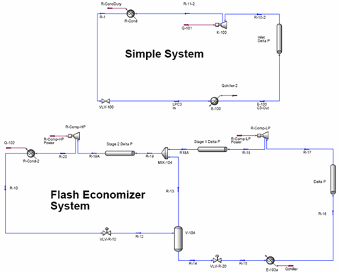
The details of a simple single-stage refrigeration system and a two-stage refrigeration system employing one flash tank economizer and HEX economizer are given in Chapter 16 of Gas Conditioning and Processing, Volume 2 [1]. The process flow diagrams for a simple system and a system with HEX economizer refrigeration are shown in Figure 1. The two stage compression with the flash tank and HEX economizers are presented in Figure 2. Note that pressure drop in different segments of the loops have been considered.

Figure 1 

Figure 2

In this TOTM, we will revisit the previous TOTM on mechanical refrigeration in which the chiller outlet temperature was kept at -35°C. Let’s consider a case in which the objective is to remove 2778 kW from the process gas at -35°C and reject it to the environment by the condenser at 35°C. The pressure drop assumptions were: in the line from the compressor discharge to the condenser and in the condenser 50 kPa, in the chiller 5 kPa and in the compressor suction line 10 kPa, between the two stages of flash economizer 20 kPa and between the flash tank and second stage of compressor 20 kPa; in the tube side and shell side of HEX economizer 20 kPa. Pure propane was used as the working fluid. An isentropic efficiency of 75 % was used in all cases. For the flash tank and HEX economizer, the optimized interstage pressure (530 kPa) which minimized the total compressor power was used. In this study, all of the simulations were performed by HYSYS software [2].

We considered the single stage (simple), single stage HEX (economizer) and the two stage (economizer) refrigeration systems. First we studied a simple refrigeration system and a single stage HEX economizer (Figure 1). The summary of simulation results is shown in Table 1. As can be seen in this table, no compressor power saving is achieved unless the HEX outlet temperature is dropped below 10 ºC due to pressure drop in the HEX. Practically, no appreciable improvement is achieved using a single stage HEX economizer. Note that the total pressure drop from chiller to the suction of compressor was assumed to be 10 kPa for the simple system and 30 kPa for the single stage HEX economizer (20 kPa pressure drop in HEX), respectively.

Table 1

Next, we studied the two stage flash tank and HEX economizer. The summary of simulation results is presented in Table 2. Total compressor power requirement is compared with the power requirement for simple system. As can be seen in this table, flash tank economizer is the most efficient which results in 14.1 % power saving (compared to simple system). For the two stage HEX economizer, the best results are obtained when the cold side approach temperature is 2 ºC.  This corresponds to 13.2 % compressor power saving. Note, this is a study in power reduction only and that CAPEX comparisons together with life cycle analysis may point towards different conclusions. The approach temperatures chosen on a HEX will have a profound effect on the area required for heat exchange (refer to Chap 13 of Gas conditioning and Processing, Vol 2).

Table 2

On reviewing Tables 1 and 2, the following observations can also be made:

  1. Single stage HEX economizer does not reduce the compressor power consumption appreciably. Its only advantage is superheating the feed to the suction of the compressor. Superheating the compressor suction will increase power requirements but decrease the likelihood of liquid carryover into the compressor.
  2. Both flash tank and HEX economizers with two-stage compression reduce the compressor power requirement by at least 12 percent.
  3. For the case of two-stage compression, the flash tank economizer is more efficient than the HEX economizer.
  4. Pressure drop in HEX economizer is an important design parameter and increases the compressor power.
  5. For the case of two-stage compression, the approach temperature in the cold side of HEX economizer affects the compressor power requirement.

To learn more about similar cases and how to minimize operational problems, we suggest attending our G4 (Gas Conditioning and Processing) and G5 (Gas Conditioning and Processing – Special) courses.

By Dr. M. Moshfeghian

Reference:

  1. Campbell, J.M., “Gas Conditioning and Processing, Vol 2: The Equipment Modules”, 8th Edition, Edited by R.A. Hubbard, John M. Campbell & Company, Norman, USA, 2000.
  2. ASPENone, Engineering Suite, HYSYS Version 2006, Aspen Technology, Inc., Cambridge, Massachusetts U.S.A., 2006.
1 response to “Flash Tank vs. HEX Economizer Refrigeration System”

  1. Hi! Do you know if they make any plugins to protect against hackers?

    I’m kinhda paranoid about losing everything I’ve worked hard on. Any recommendations?

Providing a safe work place is good business:Learn from experience

March 23, marked the three year anniversary of the BP Texas City refinery explosion.

The United States Chemical Safety Board (CSB) recently released a detailed video of the event.  The video, Anatomy of a Disaster, provides an in depth look at the incident.

Among other issues discussed, the CSB video shows what can happen when a corporate culture that values production over safety is not recognized and addressed.  As an industry, we have an obligation to provide a safe work place.  Providing a safe work place is also good business.  Every person working in our industry should learn what a generative safety culture is comprised of and strive every day to achieve that culture.

In the book Managing the Risk of Organizational Accidents, James Reason describes a generative culture as one that:

  • Actively seeks safety information
  • Trains and awards the messengers
  • Shares responsibility
  • Welcomes new ideas
  • Institute far reaching reforms when failures occur

Many of our organizations have implemented programs to try and move more toward establishing a generative culture. This change may take a significant amount of time and resources, but we owe it to ourselves and the newer generation of oil and gas industry personnel to implement and sustain this change.

An organization’s process safety management (PSM) system can provide many tools to help establish a generative culture.  Elements providing guidance on safety information, hazard assessment, incident investigation, mechanical integrity, and contractor management are closely linked to actively seeking.  Management of change and the procedures for addressing hazard assessment and incident investigation recommendations provide an avenue for evaluating new ideas and managing far reaching reforms.

Sharing the responsibility is a part of a good employee participation plan.  All personnel, from the roustabout to the chairman of the board should have a commitment to become competent within the system that has been established to manage an organization’s safety culture.

The May, 2007 Tip of the Month, mentioned a statement from the Baker Panel report of the Texas City incident.  “……People can forget to be afraid.”  The Tip of the Month now is an accident prevention pillar from the Center for Chemical Process Safety’s (CCPS) Risk Based Process Safety system.  Learn from experience.

To learn more about the CCPS accident prevention pillars and changing your organization’s safety culture, check out PetroSkills HSE courses HS 45, Risk Based Process Safety Management and HS 44 Fundamentals of Risk Assessment. Our participant centered style of training that is used in PetroSkills Facilities courses provides an outstanding environment to learn from our experiences.

By: Clyde W. Young

1 response to “Providing a safe work place is good business:Learn from experience”

  1. The top-notch of completed assembly metallic
    is highly long lasting and lasts longs. That started in order to
    be presented simply by drug business in the 1950s when that was utilized in the procedure of prostate enlargement.
    You might additionally save that swiftly when you’re not using it,
    as a result of its little size and also light-weight.

Effect of Impurities on Propane Refrigeration System – Constant Approach Temperature

In this Tip of the Month (TOTM), we will continue our discussion of the effect of working fluid impurities on the performance of refrigeration systems employing propane as the working fluid. Specifically, we will study the effect on the compressor power, the refrigerant circulation rate, and the condenser duty.

In the previous TOTM, the chiller inlet temperature was kept at -35°C but the chiller outlet temperature varied due to the presence of impurities; therefore, the approach temperature changed. In this TOTM, we will revisit the same case for constant approach temperature. In other words, the chiller outlet temperature was kept at -35°C but the chiller inlet temperature/and pressure varied due to the presence of impurities.

The details of a simple single-stage refrigeration system and a two-stage refrigeration system employing one flash tank economizer are given in Chapter 16 of Gas Conditioning and Processing, Volume 2 [1]. Similar to the previous TOTM, the process flow diagrams for the simple and with flash economizer refrigeration systems are shown in Figure 1. Note that pressure drop in different segments of the loops have been considered.

Figure 1

Let’s consider the case of the previous TOTM in which the objective was to remove 2778 kW from the process gas at -35°C and rejecting it to the environment by the condenser at 35°C. The pressure drop assumptions were: in the line from the compressor discharge to the condenser and in the condenser 50 kPa, in the chiller 5 kPa and in the compressor suction line 30 kPa, between the two stages of flash economizer 20 kPa and between the flash tank and second stage of compressor 20 kPa. Pure propane was used as the base working fluid. An isentropic efficiency of 75 % was used in all cases. For the flash tank economizer, the optimized interstage pressure which minimized the total compressor power was used. In this study, all of the simulations were performed by HYSYS software [2].

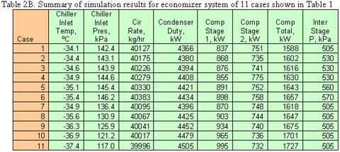
The production of propane is through fractionation of NGL; however, achieving a purity of 100% is not economical. Therefore, propane as the working fluid has normally a small fraction of ethane and butanes. We considered these components as impurities and studied their effect on the performance of the propane refrigeration system. The composition and molecular weight of the eleven cases studied are shown in Table 1. The last column represents the ratio of mixture molecular weight to the molecular weight of propane. As in the previous TOTM, we considered the single stage (simple) and the two stage (economizer) refrigeration systems. The summary of simulation results is shown in Tables 2 A&B.

Tables 1 and 2A 

Table 2B

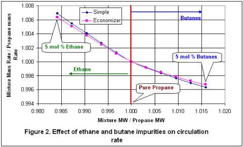
For graphical representation of the simulation results, the data in Tables 2 A&B are plotted in dimensionless form in Figures 2 through 4. Pure propane refrigeration system has been chosen as the base case and the performance of other cases are compared to the base case. Figure 2 represents the effect of ethane and butane impurities on the required circulation rate. Note that in this figure and in the subsequent figures, the y-axis is the ratio of case 2 through 11 variables (circulation rate, condenser duty or compressor power) divided by the corresponding case 1 variable, respectively.  Similarly, the x-axis is the ratio of cases 2 through 11 molecular weights to the molecular weight of case 1. Recall that case 1 is pure propane which was used as the base case.  As shown in this figure, the ethane impurity increases the circulation rate. The increasing butanes impurities cause a decrease in the circulation rate. The effect of ethane is approximately twice that of butane for a given impurity level.

Figure 2

Figures 3 and 4 represent the effect of ethane and butanes impurities on the condenser heat duty and the required compressor power requirement, respectively. These two figures indicate that both ethane and butane impurities increase the condenser duty and the compressor power requirement. It is interesting to note that the effect of butane impurities is two times higher than ethane impurities for the same level (mole fraction) of impurities.

On reviewing Figures 2 through 4, the following observation can also be made:

  1. The impurities affect the performance of the simple refrigeration systems.
  2. The trend of impurity effect is similar for the simple refrigeration system and the refrigeration system employing a flash tank economizer.
  3. In order to keep the chiller outlet temperature at the specified value, the incoming refrigerant temperature had to be decreased which resulted in lower chiller pressure (See Tables 2 A&B). This caused an increase in the compression ratio and consequently in higher compressor power consumption. Also, as the ethane impurity increases, the compressor discharge (as well as condenser) pressure increases. In case of simple refrigeration, the compressor discharge pressure increases from 1270 to 1417 kPa when ethane mole fraction is changed from 0 to 5 percent.
  4. For the case of pure propane, the compressor power and condenser heat duty are minimum.
  5. For the economizer, the feed to the first stage of the compressor is heavier than the feed to the second stage due to the mechanisms of flash separation. The heavier components go with liquid stream and the lighter components go with vapor stream.

To learn more about similar cases and how to minimize operational problems, we suggest attending our G4 (Gas Conditioning and Processing) and G5 (Gas Conditioning and Processing – Special) courses.

By Dr. M. Moshfeghian

Figures 3 and 4

Reference:

  1. Campbell, J.M., “Gas conditioning and Processing, Vol 2: The Equipment Modules”, 8th Edition, Edited by R.A. Hubbard, John M. Campbell & Company, Norman, USA, 2000.
  2. ASPENone, Engineering Suite, HYSYS Version 2006, Aspen Technology, Inc., Cambridge, Massachusetts U.S.A., 2006.

1 response to “Effect of Impurities on Propane Refrigeration System – Constant Approach Temperature”

  1. Mike Foster says:

    I’m currently operating a propane chiller with compressor suction pressure at 1.88psi, -39 f and the cold separator temp off the chiller won’t drop below -10. The design is with an Ethylene glycol injection at the tubesheet. Any thoughts on why the cold separator temp won’t drop to the designed temperature of -39? We are using a p.a.g. oil with a pour point of -48 at the expected propane dilution.

Effect of Impurities on Propane Refrigeration System

In this Tip of the Month (TOTM), we will demonstrate the effect of working fluid impurities on the performance of a simple propane refrigeration system and another one employing a flash economizer. Specifically, we will study the effect on the compressor power, the refrigerant circulation rate, and the condenser duty.

The objective of a refrigeration system is to “pump” low temperature heat from the process fluid to high temperature (ambient) where it is rejected to the environment. Energy is required to pump heat. The amount of energy depends on the quantity of heat to be “pumped’ (chiller duty) and how far the heat has to be pumped (temperature difference between the chiller and the condenser). Compression refrigeration is by far the most common mechanical refrigeration process. It has a wide range of applications in the gas processing industry. It provides chilling for:

  1. NGL extraction, LNG production, and LPG product storage
  2. Hydrocarbon and water dew point control
  3. Reflux in deethanizers/demethanizers

The details of a simple single-stage refrigeration system and a two-stage refrigeration system employing one flash tank economizer are given in Chapter 16 of Gas Conditioning and Processing, Volume 2 [1]. Similar to the previous TOTM, the process flow diagrams for the simple and with flash economizer refrigeration systems are shown in Figure 1. Note that pressure drop in different segments of the loops have been considered.

Process Flow Diagram

Figure 1. Process flow diagram for the simple and flash economizer refrigeration systems

Let’s consider the case of the previous TOTM in which the objective was to remove 2778 kW from the process gas at -35°C and rejecting it to the environment by the condenser at 35°C. The pressure drop assumptions were: in the line from the compressor discharge to the condenser and in the condenser 50 kPa, in the chiller 5 kPa and in the compressor suction line 30 kPa, between the two stages of flash economizer 20 kPa and between the flash tank and second stage of compressor 20 kPa. Pure propane was used as the base working fluid. An isentropic efficiency of 75 % was used in all cases. For the flash tank economizer, the optimized interstage pressure which minimized the total compressor power was used. In this study, all of the simulations were performed by HYSYS software [2].

The production of propane is through fractionation of NGL; however, achieving a purity of 100% is not economical. Therefore, propane as the working fluid has normally a small fraction of ethane and butanes. We considered these components as impurities and studied their effect on the performance of the propane refrigeration system. The composition and molecular weight of the eleven cases studied are shown in Table 1. The last column represents the ratio of mixture molecular weight to the molecular weight of propane. As in the previous TOTM, we considered the single stage (simple) and the two stage (economizer) refrigeration systems. The summary of simulation results is shown in Table 2.

Tables 1 and 2

For graphical representation of the simulation results, the data in Table 2 are plotted in dimensionless form in Figures 2 through 4. Pure propane refrigeration system has been chosen as the base case and the performance of other cases are compared to the base case. Figure 2 represents the effect of ethane and butane impurities on the required circulation rate. Note that in this figure and in the subsequent figures, the y-axis is the ratio of case 2 through 11 variables (circulation rate, condenser duty or compressor power) divided by the corresponding case 1 variable, respectively.  Similarly, the x-axis is the ratio of cases 2 through 11 molecular weights to the molecular weight of case 1. It should be reminded that case 1 is pure propane which was used as the base case.  As shown in this figure, contrary to butanes, the ethane impurity has no practical effect the circulation rate. The increasing butanes impurities cause a decrease in the circulation rate.

Figure 2

Figures 3 and 4 represent the effect of ethane and butanes impurities on the condenser heat duty and the required compressor power requirement, respectively. These two figures indicate that butane impurities don’t have practical effect on the condenser duty and the compressor power requirement. However, ethane impurities increase the condenser duty and the compressor power requirement. In this study, the chiller inlet temperature was kept at -35°C but the chiller outlet temperature varied due to the presence of impurities; therefore, the approach temperature changed. In the next TOTM, we will revisit this case for constant approach temperature.

On reviewing Figures 2 through 4, the following observation can also be made:

  1. The impurities affect the performance of the simple refrigeration systems.
  2. The trend of impurity effect is similar for the simple refrigeration system and the refrigeration system employing a flash tank economizer.
  3. The effect of impurities on the performance of a flash tank economizer is less pronounced than on a simple refrigeration system.

To learn more about similar cases and how to minimize operational problems, we suggest attending our G4 (Gas Conditioning and Processing) and G5 (Gas Conditioning and Processing – Special) courses.

By Dr. M. Moshfeghian

Figures 3 and 4

Reference:

  1. Campbell, J.M., “Gas conditioning and Processing, Vol 2: The Equipment Modules”, 8th Edition, Edited by R.A. Hubbard, John M. Campbell & Company, Norman, USA, 2000.
  2. ASPENone, Engineering Suite, HYSYS Version 2006, Aspen Technology, Inc., Cambridge, Massachusetts U.S.A., 2006.

3 responses to “Effect of Impurities on Propane Refrigeration System”

  1. habib ghaderi says:

    dear sir,
    send for you cycle pronpan refrigerant .

  2. Howdy, i read your webblog often of which this i own similar one with i has been just wondering if yo happen to get a few spam feedback? If that’s the result learn how to stop the objective, any plugin and something criminal background checks advise? I acquire a lot just lately it’s sending myself angry thus any specific assistance is commonly very plenty appreciated. Nonetheless, in a language, there ought a fantastic lot decent source such as this.

Refrigeration with Flash Economizer vs Simple Refrigeration System

In this Tip of the Month, we will compare the performance of a simple refrigeration system with another one employing a flash economizer. Specifically, we will evaluate compressor power saving, the effects of compressor suction–line pressure drop and the interstage pressure drop on compressor power requirement and condenser duty.

The objective of a refrigeration system is to “pump” low temperature heat from the process fluid to high temperature (ambient) where it is rejected to the environment. Energy is required to pump heat. The amount of energy depends on the quantity of heat to be “pumped’ (chiller duty) and how far the heat has to be pumped (temperature difference between the chiller and the condenser). Compression refrigeration is by far the most common mechanical refrigeration process. It has a wide range of applications in the gas processing industry. It provides chilling for:

  1. NGL extraction, LNG production, and LPG product storage
  2. Hydrocarbon and water dew point control
  3. Reflux in deethanizers/demethanizers

The details of a simple single-stage refrigeration system and a two-stage refrigeration system employing one flash tank economizer are given in Chapter 16 of Gas Conditioning and Processing, Volume 2 [1]. The process flow diagrams for the simple and with flash economizer refrigeration systems are shown in Figure 1. Note that provisions have been made to consider pressure drop in different segments of the loops.

Process Flow Diagram

Figure 1. Process flow diagram for the simple and flash economizer refrigeration systems

Let’s consider removing 1.0×10⁷ kJ/h (2778 kW) from the process gas at -35°C and rejecting it to the environment by the condenser at 35°C. Assuming 5 kPa pressure drop in the chiller, the compressor suction pressure is 132.4 kPa. The condenser pressure drop plus the pressure drop in the line from the compressor discharge to the condenser was assumed to be 50 kPa; therefore, compressor discharge pressure is 1270 kPa. Pure propane is used as the working fluid. The effect of impurities in the working will be discussed in the future Tip of the Month. In this study, all of the simulations were performed by HYSYS software [2].

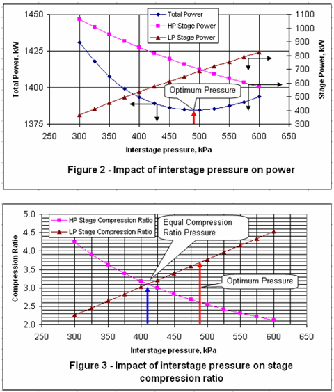
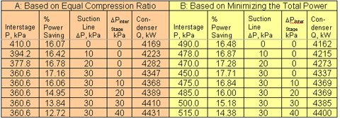
For the case of with flash economizer and assuming no pressure drop between the two stages and in the suction line, Figure 2 presents the variation of the compressor interstage and total power as a function of the interstage pressure. As can be seen in this figure, the optimum interstage pressure is about 490 kPa. This pressure corresponds to the minimum total power. However, the ideal optimum interstage pressure based on equal compression ratio can be found by Equation kPa. Figure 3 also presents the locations of these two optimum pressures.

Figures 2 and 3

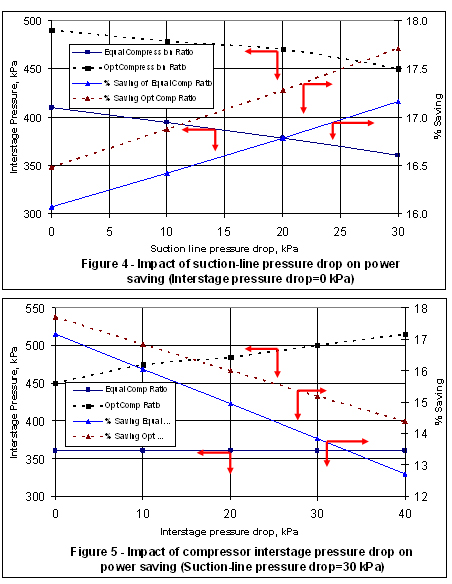
In order to study the effect of pressure drop in the compressor suction line on the total power requirement and condenser duty, the interstage pressure drop was set equal to zero. The suction line pressure drop was varied from 0 to 30 kPa with an increment of 10 kPa. Two sets of simulations were performed:

  1. The interstage pressure was determined based on the equality of compression ratio
  2. The interstage pressure was determined by minimizing the total compressor power

In each case, the total compressor power for the flash economizer system was compared with the power requirement for the simple refrigeration system and the percent of power savings were calculated.

Next, the effect of the interstage pressure drop on the total compressor power requirement and condenser duty was investigated. This was done by setting the compressor suction line pressure drop to 30 kPa and varying the interstage pressure drop from 0 to 40 kPa by an increment of 10 kPa. The load of interstage pressure drop was equally distributed between the two stages of compression. Again, the simulation results of flash economizer were compared with those of the simple refrigeration system. The summary of the results is shown in Table 1. Figures 4 and 5 are the graphical representation of the results presented in Table 1.

Table 1. Comparison of the results based on the equality of compression ratio and minimizing the total power requirement

Table 1

Table 1 indicates that the power saving ranges from 12.7 to 16.1 % when a flash economizer is used in place of the simple refrigeration system, using interstage pressure based on the equality of compression ratio. However, if the interstage pressure is determined based on minimizing the total compressor power requirement, the power saving will be from 14.4 to 16.5 %. The interstage pressure drop is unique to flash economizer and its effect is the reduction of the power saving when compared to the simple refrigeration system and increases the condenser duty.

To learn more about similar cases and how to minimize operational problems, we suggest attending our G4 (Gas Conditioning and Processing) and G5 (Gas Conditioning and Processing – Special) courses.

By Dr. M. Moshfeghian

Figures 4 and 5

Reference:

  1. Campbell, J.M., “Gas conditioning and Processing, Vol 2: The Equipment Modules”, 8th Edition, Edited by R.A. Hubbard, John M. Campbell & Company, Norman, USA, 2000.
  2. ASPENone, Engineering Suite, HYSYS Version 2006, Aspen Technology, Inc., Cambridge, Massachusetts U.S.A., 2006.

7 responses to “Refrigeration with Flash Economizer vs Simple Refrigeration System”

  1. Dear Dr. Mahmood,
    I am a Process Engineer with CH2 MHILL Abu Dhbai. I read your article and found it very interesting. I have a doubt. Let’s suppose we have 3 users at process outlet temperatures of 6°C(3rd chiller), -8°C(2nd chiller) and -24°C(1st chiller). We can achive this by C3 ref. at 3 diff pressure levels corresponding to C3 temp of 0°C, -14°C and -30°C (assuming an approach of 6°C). In this case, the vapor from the 1st chiller will be compressed to the pressure of the vapor of the 2nd chiller and these combined vapor will be compressed to the pressure of the vapor of 3rd chiller and then finally all the vapor will again be compressed. My question is, in such cases, where we have multiple users, do we have an economizer as we have in case of a single user? If we do, what will be it’s operating pressure? I will be greatful if you clear my doubt.
    Thanks,
    Rahul Mukherjee

  2. Reza says:

    Dear Dr. Moshfeghian
    Salam
    I am a process engineer and I come across your fantastic article in John Campbell website, and I really enjoy it. It would be a great honor for me to be in touch and consult with you on different cases.

    Best regards
    Reza Panahi

  3. […] M., “Refrigeration with Flash Economizer vs Simple Refrigeration System,” […]

  4. Victor says:

    At this moment I amm going away to do my breakfast, when having my breakfast
    comin yet again to read other news.

    My page – nsa encounters (Victor)

  5. Together with everything that seems to be building throughout this subject matter, all your perspectives are generally somewhat refreshing. Even so, I beg your pardon, but I can not subscribe to your entire suggestion, all be it radical none the less. It seems to everybody that your commentary are not completely validated and in simple fact you are yourself not really completely certain of the argument. In any case I did appreciate looking at it.

  6. At this time it appears like Movable Type is the best blogging platform available right now. (from what I’ve read) Is that what you are using on your blog?

  7. Minda1979 says:

    Hi blogger, do you monetize your website ? There is easy method to earn decent money every day,
    just search on youtube – How to earn $25/hour selling articles

  8. […] M., http://www.jmcampbell.com/tip-of-the-month/2008/01/refrigeration-with-flash-economizer-vs-simple-ref…,  Tip of the Month, January […]

  9. Comprehending the appropriate question to ask is actually far more important as compared to having a prepared reply. Good questions challenge your thinking. Research studies are rather lucid that we value people that pay attention to us. Our objective and goals are certainly at the heart of who we are and who we need to be. In the simplest of terms, proper questions are our instrument for aiding to see the genuine reality around us instead of murky depictions of it. Ask fundamental questions concerning the things which everybody else takes for certain. People are compassionate. They desire to have a fantastic dialog with you. We accomplish things for many different purposes. As you ask somebody about what satisfies them, it opens the entrance to discovering something that is obviously exclusively for this person. It may be a sensationa moment in time for others while you encourage them to reveal their aspirations with you. There are occassions when you don’t have to produce advice.

Acid Gas-Water Phase Behavior

In the last Tips of the Month, we discussed the phase behavior of water-sweet natural gas and water-sour natural gas mixtures. In this tip, we will demonstrate the acid gas–water phase behavior.

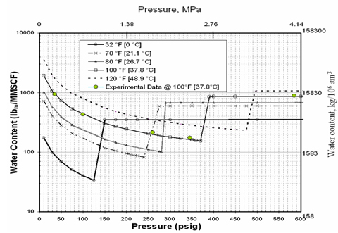
The water content of a gas depends on the system temperature, pressure and composition of the gas. The phase equilibria in the system H2S + water and CO2 + water are key to the discussion of the water content of an acid gas system. Figure 1 presents the water content of hydrogen sulfide predicted by ProMax [1] as a function of pressure and temperature.  A limited number of experimental data points at 100°F [37.8°C] by Gillespie and Wilson [2] are also shown on this diagram. The behavior shown on this plot is quite complicated and explained by Carroll [3] thoroughly: “At low pressure the hydrogen sulfide + water mixture is in the gas phase. At low pressure the water content tends to decrease with increasing pressure, which is as expected. Eventually a pressure is reached where the H2S is liquefied. On this plot this is represented by the discontinuity in the curve and a broken line joins the phase transition. There is a step change in the water content when there is a transition from vapor to liquid. In the case of hydrogen sulfide the water content of the H2S liquid is greater than the coexisting vapor. This is contrary to the behavior for light hydrocarbons where the water content in the hydrocarbon liquid is less than the coexisting vapor.”

Graph 1

Figure 1. Water content of pure H2S predicted by ProMax, experimental data [2]

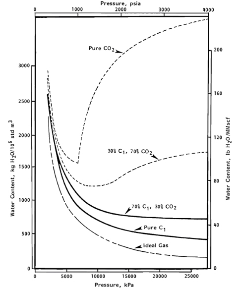
In general the phase behavior of the system CO2 + water is as complex as that of the H2S + water system. The CO2-rich liquid phase only occurs for temperatures less than about 90°F [32.2°C]. As shown in Figure 2 reported by Maddox and Lilly [4], the water content of CO2 exhibits a minimum.

Graph 2

Figure 2. Predicted saturated water contents at 100°F [38°C] for CO2, CH4 and mixture of both [4]

There are several methods available that can be used to predict the water content of acid gases. All of these methods are based on equation of state and rigorous thermodynamic models. As described above, the phase behavior is complicated and extra care should be taken to assure a correct prediction. In the remaining section of this tip, we will demonstrate the capabilities of some of these methods.

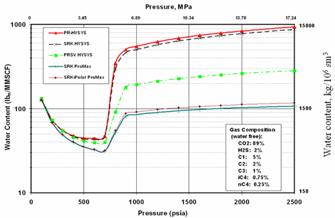
Figure 3 compares the water content calculation results for an acid gas stream by several methods in HYSYS [5] and ProMax [1]. The composition of the acid gas stream is shown in the inset of diagram. Even though at low pressures, all methods give close results, as can be seen from this figure, there are large differences at higher pressures.

Graph 3

Figure 3. Comparison of water content prediction by different methods at 59 °F [15°C]

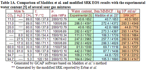
Table 1 gives another comparison of available methods for prediction of acid gas water content.

Table 1. Comparison of ProMax and modified SRK EOS results with the experimental water content [6] of several acid gas mixtures:

Table 1

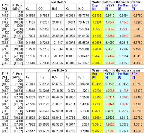
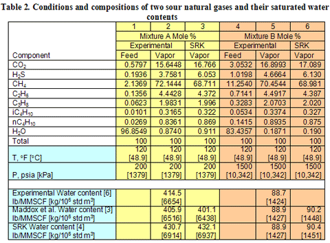
The experimental composition and predicted water content by HYSYS, ProMax and the modified SRK for eight acid gas mixtures are presented in Table 2. The upper part of this table reports the measured mole percent of the feed stream and the lower part shows the experimental vapor stream compositions in mole percent. Based on the feed compositions, three-phase flash calculations were performed and the resulting vapor stream water content (mole %) are shown in the last three columns (upper part).

For each vapor stream, the saturated water content was predicted by the above methods and is presented in the lower portion of this table. As can be seen from this table, ProMax predict saturated water content reasonably well. The red figures in Table 2 indicate that the methods predict a non-aqueous liquid phase instead of the vapor phase. Based on a dry basis phase envelope, the conditions for these mixtures were dense phase/compressed liquid.

Table 2. Conditions and compositions of 8 acid gases and their saturated water contents

Tables 2 and 3

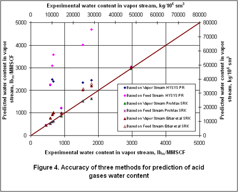
Figure 4 also compares the accuracy of the above methods graphically. This figure clearly indicates that ProMax gives the most accurate results. The Erbar et al. [7] SRK method also gives reasonable results.

Graph 4

To learn more about similar cases and how to minimize operational problems, we suggest attending

To learn more about similar cases and how to minimize operational problems, we suggest attending our G4 (Gas Conditioning and Processing)G5 (Gas Conditioning and Processing – Special)G-6 Gas Treating and Sulfur Recovery and RF-61 Refinery Gas Treating, Sour Water, Sulfur and Tail Gas courses.

By Wes Wright and M .Moshfeghian

Reference:

  1. ProMax 2.0, Bryan Research and Engineering, Inc., Bryan, Texas, U.S.A., 2007
  2. Gillespie, P.C. and G.M. Wilson, “Vapor-Liquid Equilibrium Data on Water-Substitute Gas Components: N2-H2O, H2-H2O, CO-H2O, H2-CO-H2O, and H2S-H2O” Research Report RR-41, GPA, Tulsa, OK, 1980.
  3. Carroll, J.J., “The water content of acid gas and sour gas from 100 to 220 °F and pressures to 10,000 Psia,” Presented at the 81st Annual GPA Convention, Dallas, Texas, USA, March 11-13, 2002.
  4. Maddox, R.N., L.L. Lilly, “Gas conditioning and Processing, Vol 3: Computer Applications and Production/Processing Facilities”, John M. Campbell & Company, Norman, USA, 1982.
  5. ASPENone, Engineering Suite, HYSYS Version 2006, Aspen Technology, Inc., Cambridge, Massachusetts U.S.A., 2006.
  6. Huang, S.S.-S., A.-D. Leu, H.-J. Ng, and D.B. Robinson, “The Phase Behavior of Two Mixtures of Methane, Carbon Dioxide, Hydrogen Sulfide, and Water” Fluid Phase Equil. 19, 21-32, 1985.
  7. Erbar, J.H., A.K. Jagota, S. Muthswamy, and M. Moshfeghian, “Predicting Synthetic Gas and Natural Gas Thermodynamic Properties Using a Modified Soave Redlich-Kwong Equation of State,” Gas Processor Research Report, GPA RR-42, Tulsa, USA, 1980.
  8. Ng, H.-J., C.-J. Chen, and H. Schroeder, “Water Content of Natural Gas Systems Containing Acid Gas”,Research Report RR-174, Gas Processors Association, Tulsa, OK, 2001.

2 responses to “Acid Gas-Water Phase Behavior”

  1. […] November 2007 TOTM [2], and December 2007 TOTM [3], respectively. In this TOTM, we will revisit the acid gas-water phase behavior system. Specifically, different methods of predicting water content of acid gas systems are […]

  2. I wanted to compose you one very small observation to be able to say thanks a lot again for these beautiful information you’ve provided above. It was quite remarkably generous of people like you to present unhampered all a lot of people would’ve advertised for an e book to earn some bucks on their own, most notably given that you could have tried it if you ever desired. Those ideas also served to become easy way to be certain that other individuals have the same dream like my personal own to know the truth more and more when it comes to this problem. I am sure there are thousands of more pleasant moments up front for individuals who check out your blog post.

  3. bing.com says:

    Hi, i believe that i saw you visited my website
    thus i got here to return the prefer?.I am attempting to find things to enhance my website!I guess its good enough to make use of
    some of your concepts!!

    My web site bing.com

Water-Sour Natural Gas Phase Behavior

In the last Tip of the Month, we discussed the phase behavior of water-sweet natural gas mixtures. In this tip, we will demonstrate the water-sour natural gas phase behavior. In a future tip, we will address water content of acid gases.

Water is produced with oil and gas. A question that comes to mind is: “Why is water important?” The presence of water may cause corrosion, freezing and hydrate formation. All of these problems are enhanced by the presence of acid gases such as H2S and CO2.

A phase envelope with hydrate and water dew point curves is an excellent tool to find out what form/phase water is in at operating conditions, during start-up, during shut-down and during upsets. The water content of a gas depends on the system temperature, pressure and composition of the water containing gas. There are several methods of calculating of water content of sour gases. The details of these methods can be found in Chapter 6 of Volume 1 [1] and Chapter 9 of Volume 3 [2] of “Gas Conditioning and Processing”. In this work we will use Maddox et al. [3] (Figures 6.1, 2, 3 and Equation 6.2 of Volume 1) and the modified Soave-Redlich-Kwong (SRK EoS) reported in GPA RR-42 by Erbar et al. [4]. This version of SRK is tailor-fitted to handle water-hydrocarbon systems containing hydrogen sulfide and carbon dioxide.

The compositions of several sour gases studied in this study along with their measured and predicted water contents are shown in Table 1. The Maddox et al. (referred to as Chart) results were generated using GCAP software and the modified SRK EOS results were generated by performing rigorous three-phase (gas-liquid hydrocarbons-aqueous) flash calculations. A trial version of GCAP can be downloaded here, at the bottom of the page.

Table 1 indicates that as long as the total acid gas concentrations is less than 60 mole percent, Maddox et al. and the modified SRK methods produce results within the accuracy of experimental data. However, for higher concentrations of acid gases, the modified SRK provides a better prediction.  The water content of acid gas systems will be discussed further in the next Tip of the Month.

Table 1

The composition, experimental, and predicted water content by Maddox et al. and the modified SRK for two natural gas mixtures are presented in Table 2. The upper part of columns 1, 2, 4, 5 report the measured mole percent. Based on the feed compositions shown in columns 1 and 4, three-phase flash calculations using the modified SRK were performed and the resulting vapor stream compositions are shown in columns 3 and 6, respectively. Notice that the measured and predicted vapor compositions are not identical.  Inaccuracies in predicting the vapor composition can result in errors in predicting the water saturation.

For each vapor stream, the saturated water content was predicted by both methods and is presented in the lower portion of this table. As can be seen from this table, both methods predict saturated water content reasonably well. Not surprisingly, the accuracy of both methods is improved slightly when the experimental vapor composition is used rather than the predicted vapor composition.

Table 2

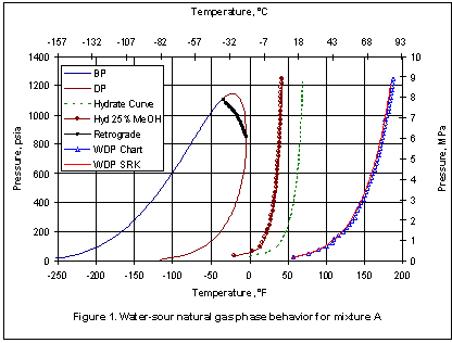
Figure 1 represents the phase behavior for mixture A. This figure includes from right to left: the water dew point, hydrate formation, 25 weight percent methanol (MeOH) inhibited hydrate formation, hydrocarbon dew point, retrograde, and the bubble point curves, respectively. The blue-triangular-symbol water dew point curve is predicted by use of Figures 6.1, 6.22 and 6.3 with Equation 6.2 of Volume 1 (Maddox et al. method). The red curve represents the water dew point predicted by rigorous calculations using the modified SRK. It is interesting to see that both methods agree quite well with each other. The region to the right of the water dew point curve is gas phase and to the left, liquid water is present.

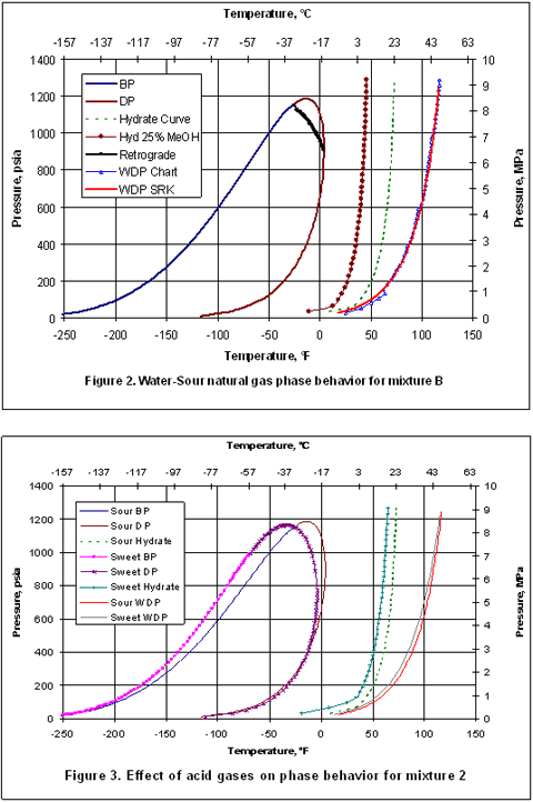
Figure 2 presents the phase behavior of sour gas mixture B. With exception of low pressure region, both methods agree quite well.

Figure 3 demonstrates the effect of acid gases on phase behavior of mixture B. As shown in this figure, the presence of acid gases shifts all of the curves to the right. In other words, the presence of acid gases increases the hydrate formation temperature considerably. It also increases the water dew point temperature. It should be noted that the water dew point curves have been generated for a fixed amount of water content predicted at specified separator condition. In this case the separator temperature and pressure were 120 °F [48.9 °C] and 1500 psia [10,342 kPa], respectively.

Figure 1

To learn more about similar cases and how to minimize operational problems, we suggest attending our G4 (Gas Conditioning and Processing)G5 (Gas Conditioning and Processing – Special) and RF-61 Refinery Gas Treating, Sour Water, Sulfur and Tail Gas courses.

Dr. Mahmood Moshfeghian

Reference:

  1. Campbell, J.M., “Gas Conditioning and Processing, Vol 1: The Basic Principles”, 8th Edition, Edited by R.A. Hubbard, John M. Campbell & Company, Norman, USA, 2001.
  2. Maddox, R.N., L.L. Lilly, “Gas conditioning and Processing, Vol 3: Computer Applications and Production/Processing Facilities”, John M. Campbell & Company, Norman, USA, 1982.
  3. Maddox, R.N., L.L. Lilly, M. Moshfeghian, and E. Elizondo, “Estimating Water Content of Sour Natural Gas Mixtures”, Laurance Reid Gas Conditioning Conference, Norman, OK, Mar., 1988.
  4. Erbar, J.H., A.K. Jagota, S. Muthswamy, and M. Moshfeghian, “Predicting Synthetic Gas and Natural Gas Thermodynamic Properties Using a Modified Soave Redlich-Kwong Equation of State,” Gas Processor Research Report, GPA RR-42, Tulsa, USA, 1980.
  5. Huang, S.S.-S., A.-D. Leu, H.-J. Ng, and D.B. Robinson, “The Phase Behavior of Two Mixtures of Methane, Carbon Dioxide, Hydrogen Sulfide, and Water” luid Phase Equil. 19, 21-32, 1985.
  6. Ng, H.-J., C.-J. Chen, and H. Schroeder, “Water Content of Natural Gas Systems Containing Acid Gas”, Research Report RR-174, Gas Processors Association, Tulsa, OK, 2001.

Figures 2 and 3

0 responses to “Water-Sour Natural Gas Phase Behavior”

  1. […] the November 2007 Tip of the Month  (TOTM), we discussed the phase behavior of water-saturated sour gases. Using limited experimental […]

  2. […] sweet, sour natural gases and acid gases–water systems. Specifically, in the November 2007 [1], February 2014 [2], and September 2014 [3] Tips of the Month (TOTM), we discussed the phase behavior of […]