In the past Tips of the Month, we discussed the phase behavior of water-free natural gas mixtures. In this tip, we will demonstrate the water-sweet natural gas phase behavior. In future tip, we will address wet sour gas.
Water is produced with oil and gas. A question that comes to mind is: “why water is important?” The presence of water may cause corrosion, freezing and hydrate formation. Hydrates can even form at warm temperatures in the presence of water. Once hydrates are formed, they are hard to remove. For design and operation of a plant it is important to know:
- Where water is in the process?
- How much water is present?
- What form/phase water is in at operating conditions, during start-up, during shut-down and during upsets?
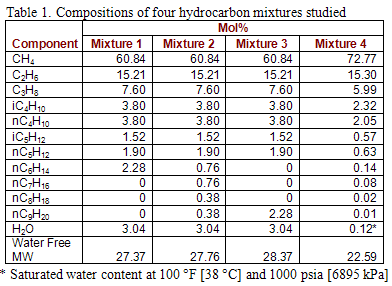
A phase envelope with hydrate and water dew point curves is an excellent tool to answer the above questions. The water content of a gas depends on the system temperature, pressure and composition of the water containing gas. There are several methods of calculating of water content. The details of these methods can be found in Chapter 6 of Volume 1 and Chapter 9 of Volume 3 of “Gas Conditioning and Processing” [1, 2]. In this work we will use Figure 6.1 of Volume 1 and the modified Soave-Redlich-Kwong (SRK EoS) reported in GPA RR-42 by Erbar et al. [3]. This version of SRK is tailor fitted for water-hydrocarbon systems. The compositions of natural gases studied in this work are shown in Table 1.
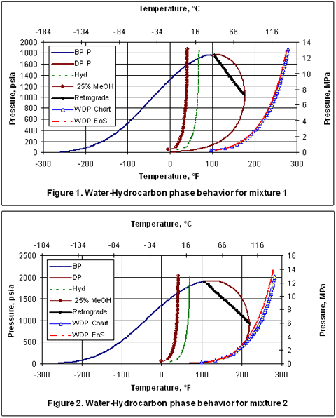
Figure 1 presents the phase behavior for mixture 1. This figure includes from right to left: the water dew point, hydrocarbon dew point, retrograde, hydrate formation, 25 weight percent methanol (MeOH) inhibited hydrate formation, and the bubble point curves, respectively. The blue-triangular-symbol water dew point curve is predicted by use of Figure 6.1 of Volume 1 and the red curve represents the water dew point predicted by rigorous calculations using the modified SRK. It is interesting to see that both methods agree quite well with each other. However, the results obtained by Figure 6.1 are somewhat more conservative. The region to the right of water dew point curve is gas phase and to the left the liquid water is present.
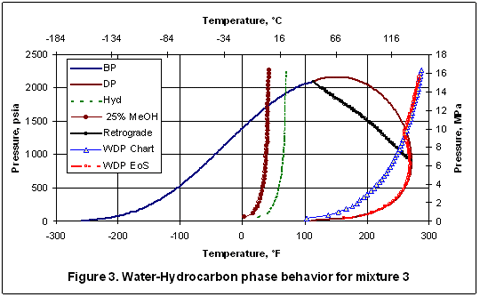
Figure 2 presents the phase behavior for mixture 2 which contains heavier compounds including nC9H20. However, the water content is the same as in mixture 1. Note the position of the water dew points did not change but, the hydrocarbon dew point curve has moved to the right, as expected, due to presence of heavier compounds. At lower pressures, the water dew point curves coincide with the hydrocarbon dew point curve. This is merely by coincidence.
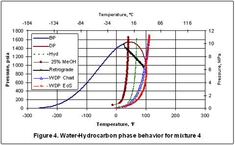
Figure 3 presents similar phase diagram for mixture 3 which is essentially the same as mixture 1 except nC6H14 has been replaced with nC9H20. Again, the hydrocarbon dew point curve shifts to the right due to presence of nC9H20.
It is interesting to note that the dry hydrocarbon dew points and the wet hydrocarbon dew points predicted by SRK coincide very closely with each other; the difference is practically negligible. Also note that at a specified pressure, the higher of the two dew points (hydrocarbon and water) have been calculated by the SRK EoS. So, below about 1400 psia [9653 kPa], the wet hydrocarbon dew point is predicted while for pressures above 1400 psia [9653 kPa], the water dew point (the higher one) is predicted.
Finally, mixture 2 has been passed through a separator at 100 °F [38 °C] and 1000 psia [6895 kPa] and the resulting vapor compositions from a three-phase flash calculation based on the SRK EoS is shown in the last column of Table 1 as mixture 4. Due to the removal of free water and heavy hydrocarbons from mixture 2, the phase envelope and the water dew point curve have moved to the left, as expected. At this condition, the water content by SRK EoS is 0.0012 mole fraction equivalent of 57 lbm/MMSCF or 914 kg/106 std. m3. Figure 4 indicates that the hydrocarbon dew point and water dew point curves intersect at 100 °F [38 °C] and 1000 psia [6895 kPa] which are the conditions of the separator.
Due to the fact that hydrate formation is controlled mostly by lighter components, there are only small variations of the hydrate formation curve and its inhibition by 25 weight percent methanol in all four mixtures.
To learn more about similar cases and how to minimize operational problems, we suggest attending our G4 (Gas Conditioning and Processing) and G5 (Gas Conditioning and Processing – Special) courses.
By: Dr. Mahmood Moshfeghian
Reference:
- Campbell, J.M., “Gas conditioning and Processing, Vol 1: The Basic Principles”, 8th Edition, Edited by R.A. Hubbard, John M. Campbell & Company, Norman, USA, 2001.
- Maddox, R.N., “Gas conditioning and Processing, Vol 3: Computer Applications and Production/Processing Facilities”, John M. Campbell & Company, Norman, USA, 1982.
- Erbar, J.H., Jagota, A.K., Muthswamy, S. and Moshfeghian, M., “Predicting Synthetic Gas and Natural Gas Thermodynamic Properties Using a Modified Soave Redlich Kwong Equation of State,” Gas Processor Research Report, GPA RR-42, Tulsa, USA, 1980.


[…] M. “Water-Sweet Natural Gas Phase behavior,” http://www.jmcampbell.com/tip-of-the-month/2007/10/water-sweet-natural-gas-phase-behavior/, […]
[…] M. “Water-Sweet Natural Gas Phase behavior,” http://www.jmcampbell.com/tip-of-the-month/2007/10/water-sweet-natural-gas-phase-behavior/, October […]
I’m impressed, I must say. Rarely do I come across a blog that’s
equally educative and entertaining, and without a doubt, you have hit the nail
on the head. The issue is something that not enough folks are speaking intelligently about.
Now i’m very happy I found this during my search for something relating to this.
please my good people of nigerians, the blood of jesus christ which he sheard for us on the corss of calveary will wash any of us who have mistakinly drink the poisnouse table water called DEW. pls my good people try nd consus of wot u eat cos this world is full of evil nd wickedness. PLS BE ALART ALL DAY. to NAFDAC, more strenth in ur work God belss u al
Discount Promotion Bitdefender Elements to Take Word When Selecting the Greatest Internet Security. Which Web Safety Has the Finest Features and Instruments?.
formation referent sante et securite au travail formation referent sante
et securite au travail acheter terbinafine formation referent sante
et securite au travail formation referent sante et securite au travail
Jika ingin mengetahui klasifikasi ini anda bisa lihat di kumpulan situs poker on the net rekening BRI
atau dikumpulan situs poker online rekening BNIatau yang lain.