In the January, February, and March 2012 tips of the month (TOTM) we discussed the transportation of carbon dioxide (CO2) in the dense phase region. We illustrated how thermophysical properties changed in the dense phase and studied their impacts on pressure drop calculations. We showed that the effect of the numerical range of values for the overall heat transfer coefficient on the pipeline temperature is significant.
In this TOTM, we will study the transportation of ethane by pipeline in the dense phase region. For a case study, a mixture of ethane containing a small fraction of methane and propane was considered. The pressure and temperature profiles along the pipelines are calculated and plotted on the feed phase envelope. In addition, the pump power requirement, pressure and temperature profiles for a single pipeline with a lead pump station are compared with the option of dividing the same line into three equal segments having one lead pump station and two intermediate pump stations.
Calculation Procedure:
For a pure compound above critical pressure and critical temperature, the system is often referred to as a “dense fluid” or “super critical fluid” to distinguish it from normal vapor and liquid (see Figure 1 for carbon dioxide in December 2009 TOTM [1]).
The same step-by-step calculation procedure described in the February 2012 TOTM [2] was used to determine the pressure and temperature profiles in a pipeline.
In the following section we will illustrate the pressure drop calculations for transporting ethane mixture in the dense phase. For details of pressure drop equations in the gas and liquid phases refer to the January 2012 TOTM [3].
Case Study:
For the purpose of illustration, we considered a case study for transporting 31393 kg/h (69209.0 lbm/hr) equivalent to 275000 tonne/y of the cited ethane mixture with the composition presented in Table 1. The mixture is available at the pressure and temperature presented in Table 1.

The following assumptions were made:
- Horizontal pipeline, no elevation change
- Steady state conditions
- The pipeline is 1380 km (858 mile) long with an inside diameter of 208.6 mm (8.212 in), onshore buried line.
- Pipeline inside surface roughness of 46 microns (0.046 mm, 0.0018 inch) which is equivalent to inside surface relative roughness (roughness factor), ε/D, of 0.00022.
- Delivery Pressure is 5.3 MPa (769 psia)
- The ground/ambient temperature, is 18.3 ˚C, (65 ˚F)
- Overall heat transfer coefficient of 2.839 W/m2-˚C (0.5 Btu/hr-ft2-˚F), for onshore buried line.
- Pump efficiency is 50%, this is the worst case, the actual pump efficiency is in the range of 50-85%).
- Simulation software: ProMax [4] and using Soave-Redlich-Kwong (SRK) [5] Equation of State.
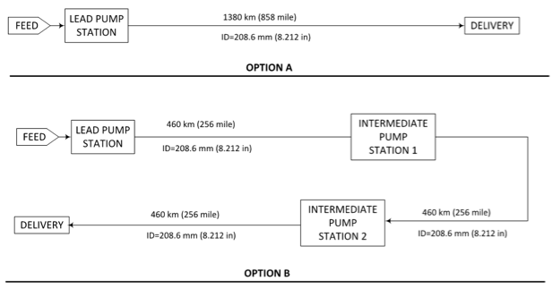
The block diagrams for two options studied are presented in Figure 1. In option A, only one pump station and a single long segment were considered. In option B, for the same pipeline and feed conditions, one lead and two intermediate pump stations with three equal pipeline segment were considered. Each segment length is 460 km (286 mile), which is 1/3 of total length and all have the same inside diameter of 208.6 mm (8.212 in). The delivery pressures for both options are the same.

Results and Discussions:
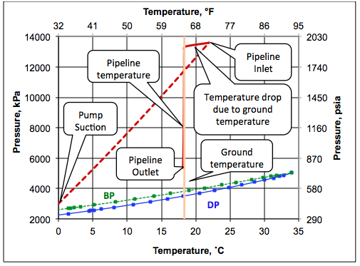
Figure 2 presents the phase envelope for the ethane mixture with the composition presented in Table 1. According to Figure 2, the feed at the pump suction conditions of 0°C (32°F) and 3000 kPa (435 psia) presented in Table 1 is in the liquid phase. In order to deliver the ethane mixture at pressure of 5.3 MPa (769 psia), for option A this liquid is pumped to a pressure of 13.6 MPa (1972 psia) before entering the pipeline. Due to pumping, the feed temperature rises from 13.6 MPa (1972 psia) before entering the pipeline. A step-by-step pump calculation with increments of 2 MPa (290 psia) for the discharge pressure reveals that the temperature rise is linear with pressure. This significant temperature rise is due to compressibility of ethane mixture.

Figure 2. Phase envelope for ethane mixture.
The pumping and pipeline pressure-temperature paths for option A are plotted on the phase envelope and presented in Figure 3. As shown in this figure, the ethane mixture at the pump discharge (pipeline inlet) is in the supercritical region (dense phase). Figure 3 indicates that as the feed enters the pipeline, its temperature drops rapidly and remains constant and very close to the ambient temperature.

Figure 3. Phase envelope, pumping path and dense phase pipeline pressure-temperature profile.
Figure 4 presents the calculated pipeline pressure profiles for options A and B. For option A, the inlet pressure is 13.6 MPa (1972 psia) to assure ethane mixture delivery at 5.3 MPa (769 psia). Similarly, in option B at each pump station the pressure is increased to 8.2 MPa (1189 psia).
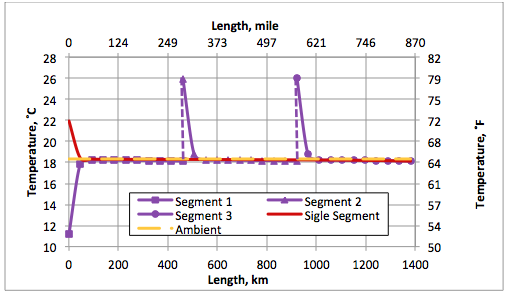
Figure 5 presents the calculated pipeline temperature profiles for options A and B. The constant ambient temperature of 18.3˚C and (65˚F) is also plotted. In option B, the discharge temperature for lead pump station is 11.2˚C, (52.1˚F) which is below the ambient temperature. For both options, the pipeline temperature rapidly approaches the ambient temperature within the first 50 km (31 mile).
Figures 6 and 7 present the density and velocity profiles along the pipeline, respectively. For a crude oil cross-country pipeline, the velocity is in the range 1.5 to 2.5 m/s (5 to 8 ft/sec). The abrupt change of density, and consequently velocity, along the first 60 km (37.3 mile) is due to the ethane mixture temperature drop, which approaches the ground temperature.

Figure 4. Pipeline pressure profiles for options A and B.

Figure 5. Pipeline temperature profiles for options A and B.

Figure 6. Pipeline fluid density profile for option A

Figure 7. Pipeline fluid velocity profile for option A
The total pump power requirements with pump efficiency of 50% for options A and B are 457 and 504 kW (381.6 and 420.8 hp), respectively. This is for screening estimate only. Normally, work is done in collaboration with the pump manufacturers for better efficiencies based on CAPEX and OPEX.
Conclusions:
Based on the results obtained for the case study considered in this TOTM, the following conclusions can be made:
- During the pumping of ethane mixture, the temperature rises linearly with pressure (Figure 2).
- The feed temperature approaches the ground temperature rapidly (Figure 5). This may not be the case for lower overall heat transfer coefficient.
- A single pipeline with only one lead pump station (option A) requires smaller pump power compared to the option of one lead pump and two intermediate pump stations (option B). Due to higher pressure in option A, wall thickness will be higher.
- A complete cost analysis of pumping requirement vs pipeline cost should be made to determine the optimum pipeline diameter, wall thickness and power requirement.
- The point not considered but worth mentioning is that ethane is very difficult to seal. We would work with pump and seal manufacturers for selecting the correct dry gas seal. This selection could determine the overall system reliability.
To learn more about similar cases and how to minimize operational problems, we suggest attending our G40 (Process/Facility Fundamentals), G4 (Gas Conditioning and Processing), PF81 (CO2 Surface Facilities), PF4 (Oil Production and Processing Facilities), and PL4 (Fundamentals of Onshore and Offshore Pipeline Systems) courses.
John M. Campbell Consulting (JMCC) offers consulting expertise on this subject and many others. For more information about the services JMCC provides, visit our website at www.jmcampbellconsulting.com, or email us at consulting@jmcampbell.com.
By: Dr. Mahmood Moshfeghian
Reference:
- Bothamley, M.E. and Moshfeghian, M., “Variation of properties in the dese phase region; Part 1 – Pure compounds,” TOTM, http://www.jmcampbell.com/tip-of-the-month/2009/12/variation-of-properties-in-the-dense-phase-region-part-1-pure-compounds/, Dec 2009.
- Moshfeghian, M., ”Transportation of CO2 in the Dense Phase,” TOTM, http://www.jmcampbell.com/tip-of-the-month/2012/02/ , Feb 2012
- Moshfeghian, M., ”Transportation of CO2 in the Dense Phase,” TOTM, http://www.jmcampbell.com/tip-of-the-month/2012/01/, Jan 2012
- ProMax 3.2, Bryan Research and Engineering, Inc, Bryan, Texas, 2014.
- Soave, G., Chem. Eng. Sci. 27, 1197-1203, 1972.

Dear Sir.
Good day and thank you for thoughtful articles. I was wondering if there was a way to estimate OPEX per inch-mile or more realistically per capacity or debit over length?
Thank you in advanced
Ali
Sir,
how to evacuate pipeline segment in case of major leak? from both ends pipeline segment liquid phase ethane evacuation w.r.t phase change (liquid phase ethane evacuation and gas ohase evacuation) as well as requirement of flare as it is denser than air and will settle out on the pipesurface.
please let me know the evacuation/ blowdown procedure?
Thanks for this Tip Of the Month.
I will like to be receiving your totm mais
this passage is persian for Dr mahmood moshfeghian
salam be hamvatane aziz. bayad goft ke ba didane esmetoon kheili ehsase ghoroor kardam…
sharmande age englisi nanveshtam. rastesh man danshjooye mohandesiye nafte daneshgahe tehran hastam. mota’asefane sharayate bade amoozeshi dar inja kheili mano zade karde va be shedat az lahaze nomre va kamiat oft kardam vali hamchenan dar yadgiriye darsam ba ghodrat pish miram. az shomadarkhaste komak va rahnmai daram ta betoonam ye joori dar yek daneshgahe khareji tahsilatamo edame bedam…
khieli be komak ehtiaj daram…
pisshapish azatoon sepasgozaram.
mokhlese shoma rahmani
Dear,
Thanks a lot; there are a lot informations from you.
Concern abrupt despressurization, I ask, the pipeline spec must have for -90C ? Or we can spec for -45C ?
Thanks,
Afonso
Dear Sir,
Thank you for the useful information.
I would like to ask a question regarding prime criteria to be considered in selecting block valve station for liquid ethane pipeline.
Regards,
Mohamed Ibrahim
Good day and thank you for thoughtful articles. Plese, what´s the pipeline material ? spec for -29 C ? or -90 C ? Or ) C?
Thanks lot.
Afonso
Good day and thank you for thoughtful articles. Please, what´s the pipeline material ? the spec for 0 C ? or -29 C or -45 C or -90C ?
Thanks lot.
Afonso
Highly descriptive article, I loved that bit. Will there be a part 2?
Appreciation to my father who informed me regarding this website, this website is in fact amazing.
Gentlemen,
I read your article “Transportation of Ethane by Pipeline(Dense Phase)” and have a question about the temperature rise across the pumps. Your article, from the graph, indicates a 14 Deg F increase. Most equations I use generate a temperature increase from
a) Pump inefficiency or
b) Change in Heat Capacity
Considering your stated efficiency of 50%, our equations would only increase the temperature by 2 or 3 Deg F.
Our equations considering Change in Heat Capacity would calculate an increase the temperature of 5 Deg F. We use a Cp of 1.113 on the suction side and calculate a Cp of 1.03 on the discharge side. We are using NIST for the fluid properties and calculate
Cp discharge = Cp suction*(1 + (DCp/DP)*Dp + (DCP/DT)*DT. The derivatives are calculated using NIST.
Can you explain our differences?
Do you use the ProMax 3.2 program from Bryan Research and Engineering to perform these simulations?
Thanks in advance for any help or guidance.
Peter N. Linden, PE
Linden Professional Services, Inc.
9103 Brahms Lane
Houston, Texas 77040
713-937-7875
Hi Peter,
A manual calculation leads to same temp rise as shown in Dr. Moshfeghian paper if you consider an efficiency of 50% BHP at pump end ( which I believe could be higher e.g. 70 % regarding service condition and using centrifugal pump.The high temp. rise when pumping light HC like C2 is due to lower heat capacity resulting in higher temp rise for removing almost same amount of heat generated by friction etc. compared to other pumping application eg. water. : However there is an error in the paper re. Hp to KW conversion. Also pls. remember as you are pumping C2 then you are dealing with liquid C2 not the gas therefore liquid heat capacity of C2 shall be used in the following formula:
dt = Ps (1 – μ) / (cp q ρ) (1)
where
dt = temperature rise in the pump (oC)
q = volume flow through the pump (m3/s)
Ps = brake power (kW)
cp = specific heat capacity of the fluid (kJ/kgoC)
μ = pump efficiency
ρ = fluid density (kg/m3)
Right now it appears like WordPress is the best blogging platform available right now. (from what I’ve read) Is that what you’re using on your blog?
I believe one of your ads caused my internet browser to resize, you might want to put that on your blacklist.
“Great article.Really looking forward to read more.”
Sir, have you published similar article for transporting/handling of ethylene in dense phase? If so, could you please send me the link. Thank you for your help.