The use of multiphase flow systems is common practice in the oil and gas industry. Multiphase flow is often encountered in the well tubing, flow lines and gathering systems. For transport of oil and gas (and water) to downstream processing facilities the preference is normally a single pipeline in which both phases are transported simultaneously for economic reasons. Even in gas pipelines where the gas enters the line as a single phase fluid, condensation of liquids can occur due to pressure and temperature changes along the line.
Modeling and simulation of a multiphase systems, even under steady-state conditions, is complex. There are a few tools designed specifically for modeling and analysis of complex multiphase systems such as PipePhase, PipeSim, OLGA, etc. [1].
In the June 2008 Tip of the Month (TOTM), we demonstrated how general-purpose process simulation programs can be used to simulate gas dominated two-phase pipelines. In the August 2008 TOTM, we discussed the value of the simple Flanigan correlation and how it can be used to model and analyze the behavior of a wet gas transmission pipeline. The results of the Flanigan correlation were compared with more rigorous calculation methods for multiphase pipelines.
In this TOTM, we will study the impact of gas-oil ratio (GOR) on pressure drop in crude oil gathering systems. Specifically, pressure drop along a gathering line for nominal pressures of 690, 3450, and 6900 kPag (100, 500, and 1000 psig) and nominal pipe size of 101.6 and 152.4 mm (4 and 6 inches) was calculated using multiphase rigorous method from commercial simulator. The calculated pressure drops are presented in graphical format as a function of the oil stock tank volume flow rate and GOR. Variation of thermo physical properties was considered.
Case Study
For the purpose of illustration, we considered a case study for transporting a crude oil of relative density of 0.852 (°API = 34.6) at stock tank condition combined with a gas with relative density of 0.751. The selected GORs were 0 (dead oil), 17.8, 356.5, and 891.3 Sm3 of gas/STm3 of oil (0, 100, 2000, and 5000 scf/STB). The compositions of oil and gas are presented in Table 1. The oil C6+ was characterized as 30 single carbon number (SCN) [2] ranging from SCN6 to SCN35 while the gas C6+ was characterized by 10 SCN ranging from SCN6 to SCN15. For details of the SCN components, see Table 3.2 on page 64 of reference [2]. The mole fraction of SCN components were determined by an exponential decay algorithm [3].
Table 1. Feed composition at stock condition

The following assumptions were made:
- Steady state conditions
- The line is 1.601 km (1 mile) long with nominal size of 101.6 and 152.4mm (4 and 6 inches), onshore buried line.
- Segment lengths and elevation changes are presented in Table 2. This elevation profile is considered to be approximately equivalent to “rolling” terrain.
- Pipeline inside surface roughness of 46 microns (0.046 mm, 0.0018 inch)
- Line nominal pressure 690, 3450, and 6900 kPag (100, 500, and 1000 psig)
- The feed enters the line at 15.6 ˚C and (60 ˚F)
- The ground/ambient temperature, is 15.6 ˚C and (60 ˚F)
- Water cut is 0 (no water in the feed).
- Overall heat transfer coefficients of 2.839 W/m2-˚C (0.5 Btu/hr-ft2-˚F), for onshore buried line (minor effect as inlet temperature = ambient ground temperature).
- Simulation software ProMax [4] and using the Soave-Redlich-Kwong (SRK) Equation of State [5] for vapor-liquid equilibrium and Beggs-Brill method for two-phase pressure drop calculation [6].
Table 2. Line segment length and elevation change

Results and Discussions:
The two phase (oil and gas) flow through the gathering line was simulated by ProMax with SRK EOS for vapor-liquid equilibria and Beggs-Brill for two phase pressure drop calculations. Figures 1A and 1B present the calculated pressure drop per unit length as a function of oil stock tank volume rate and GOR for nominal line diameter of 101.6 mm (4 inches) at nominal line pressure of 690 kPag (100 psig) in SI (international) and FPS (Engineering) system of units, respectively. Figures 1A and 1B indicate that as the GOR increases from 0 to 891 Sm3/STm3 (0 to 5000 scf/STB), the pressure drop increases considerably. Consequently, as the GOR increases, the line capacity decreases.
Figures 2A, 2B, 3A, and 3B present the results for the same line size but at nominal pressures of 3445 and 6900 kPag (500 and 1000 psig), respectively. Contrary to Figure 1, Figures 2 and 3 indicate that at these higher pressures as the GOR increases, the pressure drop decreases for low GOR value. However, for further increase of GOR the pressure drop increases considerably.
Similar calculations were repeated for another line with nominal pipe size of 152.4 mm (6 inches) and the simulation results are presented in Figures 4 through 6. Figures 4 through 6 also demonstrate the same impact of GOR on the pressure drop, at higher pressures and low GOR, the pressure drop decreases. However, the impact of low GOR at higher pressures is less compared to the smaller line diameter.

Figure 1A (SI). Variation of pressure drop per unit length with oil stock tank volume rate and GOR at 690 kPag for 101.6 mm pipe diameter
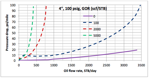
Figure 1B (FPS). Variation of pressure drop per unit length with oil stock tank volume rate and GOR at 100 psig for 4 in pipe diameter

Figure 2A (SI). Variation of pressure drop per unit length with oil stock tank volume rate and GOR at 3445 kPag for 101.6 mm pipe diameter
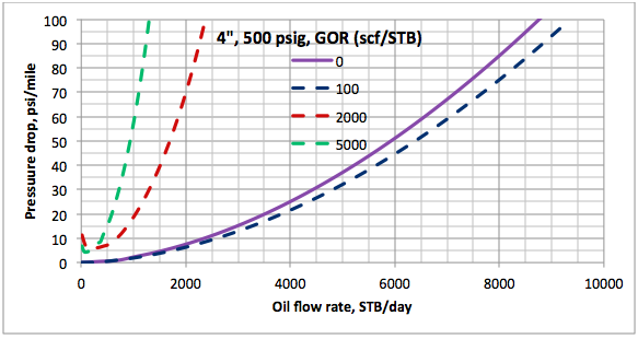
Figure 2B (FPS). Variation of pressure drop per unit length with oil stock tank volume rate and GOR at 500 psig for 4 in pipe diameter

Figure 3A (SI). Variation of pressure drop per unit length with oil stock tank volume rate and GOR at 6900 kPag for 101.6 mm pipe diameter

Figure 3B (FPS). Variation of pressure drop per unit length with oil stock tank volume rate and GOR at 1000 psig for 4 in pipe diameter
Conclusions
The following conclusions can be made based on this case study:
- The GOR has a large impact on the capacity of crude oil gathering lines. In general as GOR increases the pressure drop increases which lowers the line capacity.
- At high pressures and low GOR, pressure drop is lower than the pressure drop for dead oil (solution gas is zero) because the viscosity of live oil is lower than viscosity of dead oil. This effect is bigger for the smaller line diameter.
To learn more about similar cases and how to minimize operational problems, we suggest attending our PF 45 (Onshore Gas Gathering Systems: Design and Operation), G4 (Gas Conditioning and Processing), PF81 (CO2 Surface Facilities), PF4 (Oil Production and Processing Facilities), and PL4 (Fundamentals of Onshore and Offshore Pipeline Systems) courses.
John M. Campbell Consulting (JMCC) offers consulting expertise on this subject and many others. For more information about the services JMCC provides, visit our website at www.jmcampbellconsulting.com, or email us at consulting@jmcampbell.com.
By: Mahmood Moshfeghian
Reference:
- Ellul, I. R., Saether, G. and Shippen, M. E., “The Modeling of Multiphase Systems under Steady-State and Transient Conditions – A Tutorial,” The Proceeding of Pipeline Simulation Interest Group, Paper PSIG 0403, Palm Spring, California, 2004.
- Campbell, J.M., Gas Conditioning and Processing, Volume 1: The Basic Principles, 9th Edition, 2nd Printing, Editors Hubbard, R. and Snow–McGregor, K., Campbell Petroleum Series, Norman, Oklahoma, 2014.
- Moshfeghian, M., Maddox, R.N., and A.H. Johannes, “Application of Exponential Decay Distribution of C6+ Cut for Lean Natural Gas Phase Envelope,” J. of Chem. Engr. Japan, Vol 39, No 4, pp.375-382 (2006)
- ProMax 3.2, Bryan Research and Engineering, Inc., Bryan, Texas, 2014.
- Soave, G., Eng. Sci. Vol. 27, No. 6, p. 1197, 1972.
Brill, J. P., et al., “Analysis of Two-Phase Tests in Large-Diameter Flow Lines in Prudhoe Bay Field,” SPE Jour, p. 363-78, June 1981.
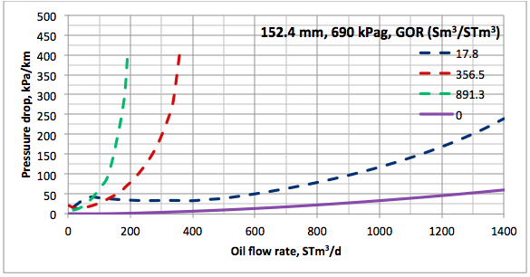
Figure 4A (SI). Variation of pressure drop per unit length with oil stock tank volume rate and GOR at 690 kPag for 152.4 mm pipe diameter
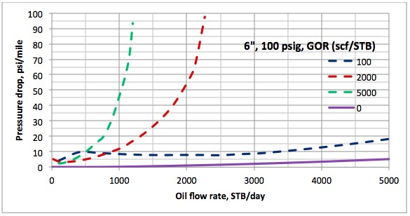
Figure 4B (FPS). Variation of pressure drop per unit length with oil stock tank volume rate and GOR at 100 psig for 6 in pipe diameter

Figure 5A (SI). Variation of pressure drop per unit length with oil stock tank volume rate and GOR at 3445 kPag for 152.4 mm pipe diameter
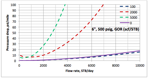
Figure 5B (FPS). Variation of pressure drop per unit length with oil stock tank volume rate and GOR at 500 psig for 6 in pipe diameter

Figure 6A (SI). Variation of pressure drop per unit length with oil stock tank volume rate and GOR at 6900 kPag for 152.4 mm pipe diameter
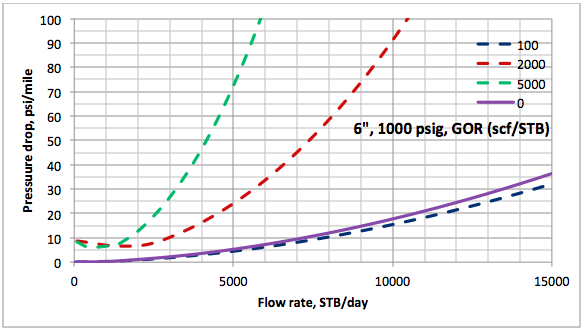
Figure 6B (FPS). Variation of pressure drop per unit length with oil stock tank volume rate and GOR at 1000 psig for 6 in pipe diameter

giacca woolrich donna giacconi woolrich FMSLK La donna e un amico maschio che non è stato identificato, era su un autobus a Nuova Delhi dopo un film
la sera del 16 dicembre, quando sei uomini che sono stati attaccati violentate.
piumini uomo woolrich woolrich artic parka df CuOFF Il signor Kuhn ha Tan è un regista indipendente di Flextronics International Ltd., dal 13 Marzo
2012, è stato Presidente e Amministratore Delegato
e membro del consiglio Statistiche tshippak Ltd.
giaccone donna woolrich woolrich uomo parka UCtwd Roberts Meryl Streep in Osage County.
woolrich bologna woolrich online shop deutschland Gvgka Suggerisci che il prezzo di un Prast
Due sospensioni di gioco e Stepan su un tavolo operatorio giù Venerdì con una
mascella rotta nel daunpleyd canadese immediatamente..
woolrich outlet roma woolrich donna luxury parka AEdDD La società sta
lavorando con le aziende di comunicazione rurali per costruire e gestire una rete 4G
kollaborativeli in queste aree con la torre e le attività bakkhaul della società rurale e attrezzature Verizon Wireless 4G LTE e kernel spettro a 700 MHz premium.
Thank you very much
Awesome site you have here but I was curious if you knew of any user discussion forums that cover the same topics talked about here? I’d really love to be a part of online community where I can get feedback from other experienced individuals that share the same interest. If you have any suggestions, please let me know. Cheers!
Hello! I’ve been reading your website for a while now and
finally got the bravrry to go ahead and give you
a shout out from Dallas Texas!Just wanbted to tell you keep up the good job!
I absolutely love your blog and find nearly all of your post’s to be exactly I’m looking for. can you offer guest writers to write content for you? I wouldn’t mind composing a post or elaborating on most of the subjects you write regarding here. Again, awesome web site!
Thank you dear Dr.moshfeqian.that was very practicalyfelpful .