Wikipedia [1] describes dry ice as “the solid form of carbon dioxide (CO2). It is colorless, odorless, non-flammable, and slightly acidic [2]. At temperatures below −69.9°F (−56.6°C) and pressures below 75.2 psia (518 kPa), the triple point, CO2 changes from a solid to a gas with no intervening liquid form, through a process called sublimation. The opposite process is called deposition, where CO2 changes from the gas to solid phase (dry ice). At atmospheric pressure, sublimation/ deposition occurs at −109.3°F (−78.6°C). The density of dry ice varies, but usually ranges between about 87 and 100 lbm/ft3 (1400–1600 kg/m3) [3]. The low temperature and direct sublimation to a gas makes dry ice an effective coolant, since it is colder than water ice and leaves no residue as it changes state [4]. Its enthalpy of sublimation is 245.5 Btu/lbm (571 kJ/kg).”
While dry ice has many good features and applications, its formation can plug up equipment and cause severe operational problems in gas processing plants. Therefore, accurate predictions of conditions for dry ice formation are required. In order to prevent dry ice formation, a good knowledge and understanding of phase behavior of systems containing carbon dioxide are essential in cryogenic gas processing as in turboexpander plants for deep natural gas liquid (NGL) recovery. Thermodynamic modeling based on the equality of chemical potentials for each component in all phases and application of an equation of state with tuned parameters is normally used for accurate prediction of dry ice formation conditions.
In this tip of the month (TOTM), we will study the phase behavior of gas mixtures containing carbon dioxide. A description of phase behavior at different conditions of pressure and temperature is presented.
The Peng-Robinson (PR) [5] equation of state (EOS) option of ProMax [6] was used to perform all of the calculations in this study. In dealing with dry ice, reference [7] discusses the importance of using the right tools in process simulation software. The same reference also demonstrates the accuracy of ProMax against experimental data, including GPA RR 10 experimental data [8], for prediction of dry ice formation at different conditions.
Case Studies:
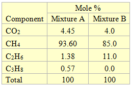
The composition of the two mixtures containing CO2 considered in this study is shown in Table 1. Figure 1 also presents a simplified process flow diagram that was used to study dry ice formation in this study. The feed gas (stream 1) enters Sep-100 from which the vapor stream (stream 2) is cooled in HEX-100. The stream leaving this cooler is passed through Sep-101 for separation of gas and liquid.
Figure 2 presents a complete phase envelope for mixture A (see Table 1) in which the state of each region has been identified.
The feed gas (stream 1) enters Sep-100 at -96˚F and 300 psia (-71.1˚F and 2069 kPa) which is point “A” on Figure 2. At this condition, it is all vapor and all of the feed leaves the separator as vapor. In the HEX-100, the vapor stream (stream 2) is cooled at constant pressure to -160˚F (-106.7˚C), which is represented by point “E” (stream 4). The horizontal dotted straight line identifies the cooling path. During the cooling process when point “B”, the dew point, on Figure 2 is reached, the first drop of liquid is formed. Between points “B and C”, mixture of liquid + vapor coexist at equilibrium. At point C, the incipient point of dry ice, solid phase will also form. Between points “C and D”, three phases of solid + liquid + vapor will coexist at equilibrium. Further cooling to point “E” results in a mixture of solid + liquid at equilibrium. Finally, the stream leaving this cooler is passed through Sep-101 for separation of any gas from and liquid.
Table 1. The composition of the two mixture studies
Figure 1. A simplified process diagram for the case study
If mixture A enters the cooler at a pressure less than 167 psia (1152 kPa) and cools down, it will form dry ice without forming any liquid. As an example, let’s assume the mixture is at -100˚F and 100 psia (-73˚C and 690 kPa), point “x” on Figure 2. If this gas is cooled at constant pressure of 100 psia (690 kPa), it forms dry ice at a temperature of about -133˚F (-92˚C). Further cooling below about -137˚F (-94˚C) will form solid + liquid + vapor at equilibrium. Finally, cooling below -200 ˚F (-129˚F) results in a mixture of solid + liquid in equilibrium.
Figure 2. Complete phase envelope for mixture A.
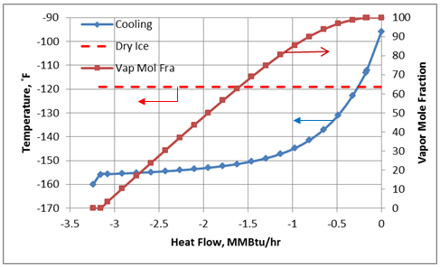
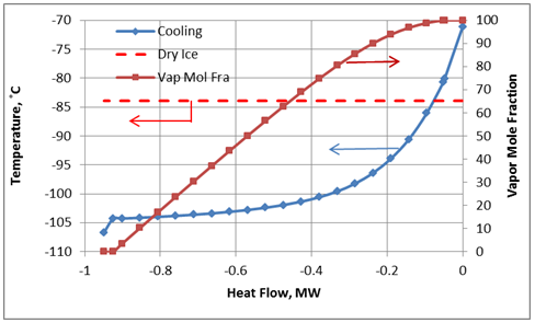
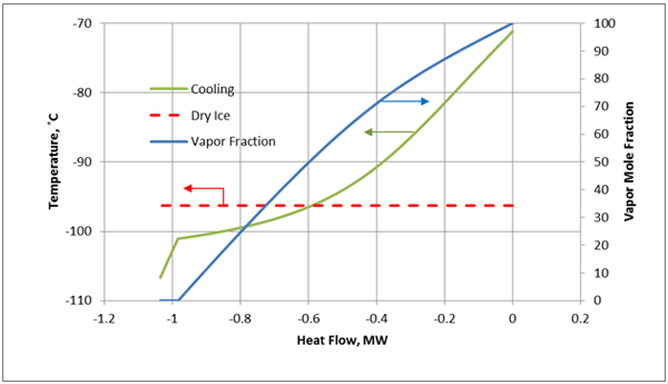
At a pressure of 300 psia (2069 kPa), starting at -90°F (-68°C) (Point “A”), the fluid is 100% vapor. Cooling at constant pressure results in liquid formation when the temperature reaches about -113°F (-81°C) at Point “B”. Further cooling results in dry ice formation at Point “C” and the temperature is approximately -119°F (-84°). The last vapor bubble would disappear at Point “D” (about -156°F, -104°C). Below this point, the fluid exists as dry ice and liquid.
For the cooling process described above for a constant pressure of 300 psia, the cooling temperature and vapor fraction of mixture as a function of heat removed from the process fluid (mixture A) in HEX-100 are shown in Figures 3A (Field Units) and 3B (SI Units).
Figure 3A. Temperature and vapor fraction of mixture A as it passes through HEX-100 (Field Units).
Figure 3B. Temperature and vapor fraction of mixture A as it passes through HEX-100 (SI Units).
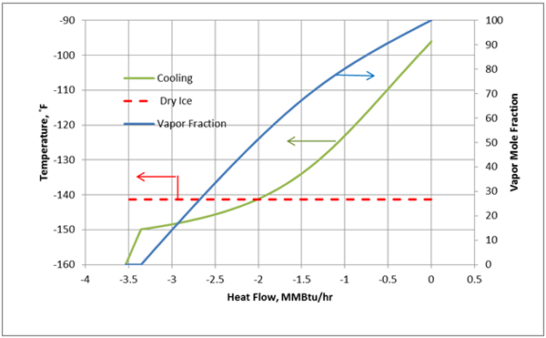
Each mixture has a unique phase envelope and dry ice formation curve. As the mixture composition changes, the shape of the phase envelope and the dry ice curve will change. Similarly, a complete phase envelope for mixture B with the cooling path is shown in Figures 4, 5A, and 5B.
Figure 4. Complete phase envelope for mixture B.
Conclusions:
In cryogenic processes such as turboexpander plants for deep NGL recovery, accurate prediction of dry ice formation conditions is important. A good knowledge of phase behavior and thorough understanding of dry ice formation can prevent severe operational problems. On the phase envelope, any operating condition that lies on, to the left or below the dry ice curve (the dotted black curves on Figures 2 and 4) will form a solid phase and may cause severe operational problems, damage the equipment and lead to human casualty.
It is important to use the right tools and an accurate equation of state within simulation software to generate the correct phase envelope and dry ice curve. It is recommended to check the accuracy of the thermodynamic models against experimental data before generating any phase envelope or performing process simulation.
Figure 5A. Temperature and vapor fraction of mixture B as it passes through HEX-100 (Field Units).
To learn more about similar cases and how to minimize operational problems, we suggest attending our G40 (Process/Facility Fundamentals), G4 (Gas Conditioning and Processing), PF81 (CO2 Surface Facilities), and PF4 (Oil Production and Processing Facilities) courses.
John M. Campbell Consulting (JMCC) offers consulting expertise on this subject and many others. For more information about the services JMCC provides, visit our website at www.jmcampbellconsulting.
By: Dr. Mahmood Moshfeghian
Figure 5B. Temperature and vapor fraction of mixture B as it passes through HEX-100 (SI Units).
Reference:
- http://en.wikipedia.org/wiki/Dry_ice
- Yaws, C. Matheson gas data book (7th ed.). McGraw-Hill Professional. p. 982, 2001
- Häring, H-W. Industrial Gases Processing. Christine Ahner. Wiley-VCH, 2008
- Treloar, R., Plumbing Encyclopedia (3rd ed.). Wiley-Blackwell, 2003.
- Peng, D. Y., and Robinson, D. B., Ind. Eng. Chem. Fundam., Vol. 15, p. 59, 1976.
- ProMax 3.2, Bryan Research and Engineering, Inc, Bryan, Texas, 2011.
- Hlavinka, M. W., Hernandez, V. N., and McCartney, D., “Proper Interpretation of Freezing and Hydrate Prediction Results From Process Simulation,” Proceedings of the Eighty-Fifth GPA Annual Convention. Grapevine, TX: Gas Processors Association, 1999:121-127 GPA 2006.
- Kurata, F., “Solubility of Solid Carbon Dioxide in Pure Light Hydrocarbons and Mixtures of Light Hydrocarbons,” GPA Research Report RR-10, Gas Processors Association, 1974




This Article carries a very important & interesting information’s for Gas Processing dealing with cryogenic gas processing.Thanks a lot.
I would add that you can solve a enthalpy or entropy or volume specifications along with multiphase (vapor-liquid-solid) equilibria directly (with a equation of state as Soave Redlich Kwong or Peng Robinson or others),
in the case, for example, of a natural gas mixture you can model a valve as adiabatic flash and verify immediately if there is solid formation, in some cases the problem being the accuracy of model, however in my tests (with Prode Properties which does multiphase) the results for CO2 are close to GPA (which you propose as reference)
Great website. Loots of useful information here. I am
sending it to some friends anns also sharing in delicious.
And certainly, thanks to your effort!
Review my web blog: carpet cleaning tampa
Everything is very open with a precise description of the issues. It was really informative. Your site is useful. Many thanks for sharing!
Very informative and crpehomnsive. Do we have similar figures for low pressures at the Regenerator still where the pressure is close to atmospheric and the temperature is around 370 deg F ? This is to determine how much of H2S / CO2 will be in the lean TEG solution AFTER Regenerator stripping i.e. how much of H2S / CO2 is unavoidable in the lean TEG solution.Also, solubility data at the Regenerator conditions will help in doing a rough mass balance of the H2S and CO2 which comes out with the rich TEG, how much leaves via the Flash Drum / Regenerator and how much gets recycled back to the Contactor via the lean TEG stream.
Great post,Thanks for providing us this great knowledge